Heart valve holder assembly for use in valve implantation procedures

a technology for a heart valve and a holder, which is applied in the field of holding systems or mechanisms, can solve the problems of different constraints, unfavorable stent insertion, and aortic and pulmonary prosthetic heart valve implantation, so as to reduce the time of cardiopulmonary bypass, facilitate the implantation process, and increase the space available

Active Publication Date: 2012-09-25
MEDTRONIC INC
View PDF95 Cites 35 Cited by
  • Summary
  • Abstract
  • Description
  • Claims
  • Application Information

AI Technical Summary

Benefits of technology

[0010]The present invention is directed to a valve holder assembly that is attachable to a bioprosthesis to assist a surgeon during implantation of a heart valve. In particular, the valve holder of the invention can be used for aortic valve replacement, and provides for temporary deflection of stent posts of the prosthesis, such as an aortic prosthetic heart valve. This deflection of the stent posts helps to ease the implantation process, and also increases the space available for the surgeon to manipulate the sutures and tie suture knots. Other benefits include, but are not limited to: reduced cardiopulmonary bypass time; reduced potential for injury to patient's aorta during knot tying; the ability to implant a properly sized valve and the resultant hemodynamic benefit; increased visibility to knots and a resultant reduction in potential for paravalvular leakage; and potential for less damage to the prosthetic valve during knot tying due to insufficient access.
[0011]In one aspect of the invention, a valve holder assembly is provided that includes three separate ratchet sutures for distributing the stresses involved with winding the sutures around a rotor to inwardly deflect three commissure posts of a prosthetic heart valve. This stress distribution can help to prevent or minimize the occurrences of suture breakage during ratcheting of the rotor to deflect the stent posts inward, and also during the process of implanting the prosthetic valve into a patient. In order to accomplish this stress distribution, the rotor and its associated holder are provided with structure that includes a number of specifically positioned holes for a certain path for suture routing. In at least one aspect of the invention, the total number of sutures used for both attaching a holder to a stent ring and for attaching commissure posts to a rotor for deflection of the posts is equal to the number of commissure posts. Typically, the number of commissure posts is three, although there can be more or less than three commissure posts. In addition, in at least some of the embodiments of the invention, the height and leg profile are configured to minimize the overall size of the valve holder assembly. The valve holder assemblies can further be provided with features to minimize or prevent rotor wobble within the holder of a valve holder assembly, and to minimize or prevent “spinning” of the handle relative to the valve holder assembly to which it is mounted.

Problems solved by technology

Implantation of a stented prosthetic heart valve presents certain technical challenges.
However, due to a lack of visibility through the prosthetic valve, a surgeon can inadvertently loop sutures around the stent posts during suturing of the annular suture ring portion of the prosthesis.
Similarly, the extending stent posts may undesirably “snag” on chordae or trabeculae inside the left ventricular cavity.
Aortic and pulmonic prosthetic heart valve implantation, however, presents different constraints from those associated with mitral or tricuspid valve replacement because there is less room for the surgeon to maneuver during the surgery.
However, the proximally extending stent posts associated with the stented prosthesis still can interfere with the various other maneuvers required of the surgeon.
Unfortunately, the above-described mitral and tricuspid prosthetic heart valve holders are of little value for aortic and pulmonic valve replacement procedures in that these holders position the holder and handle to extend in a direction opposite from that of the stent posts.

Method used


Image

  • Heart valve holder assembly for use in valve implantation procedures
  • Heart valve holder assembly for use in valve implantation procedures
  • Heart valve holder assembly for use in valve implantation procedures

Examples


Embodiment Construction

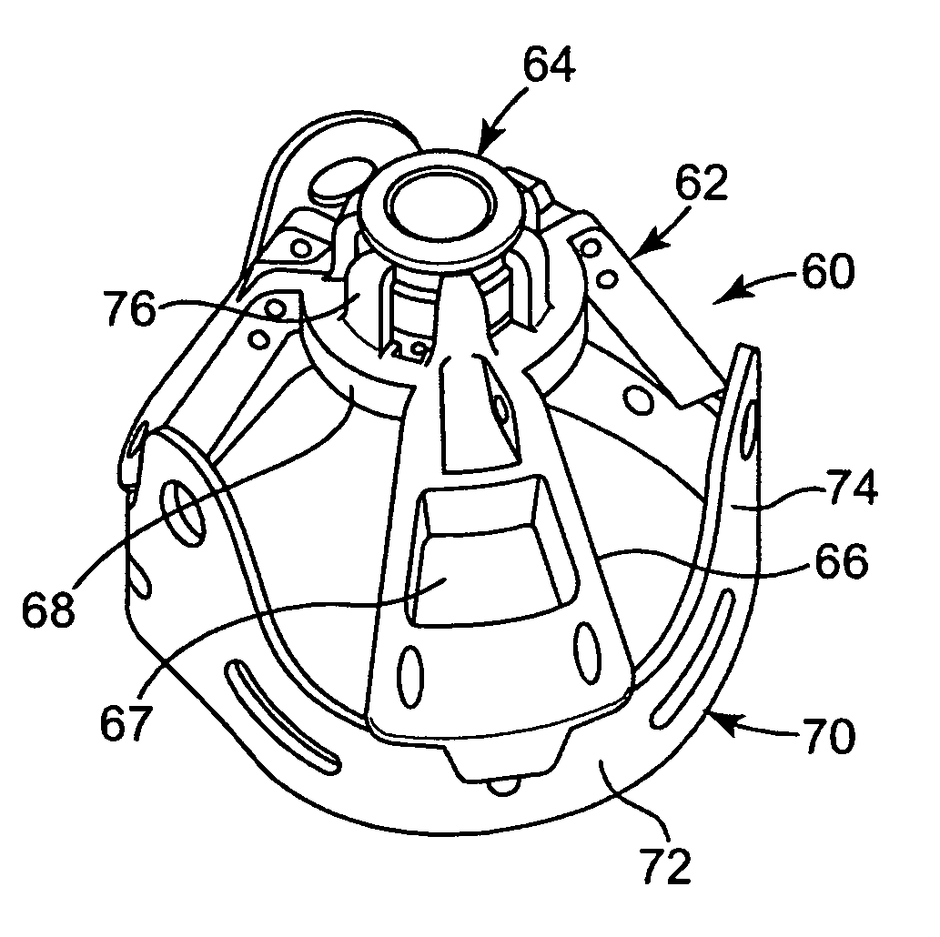
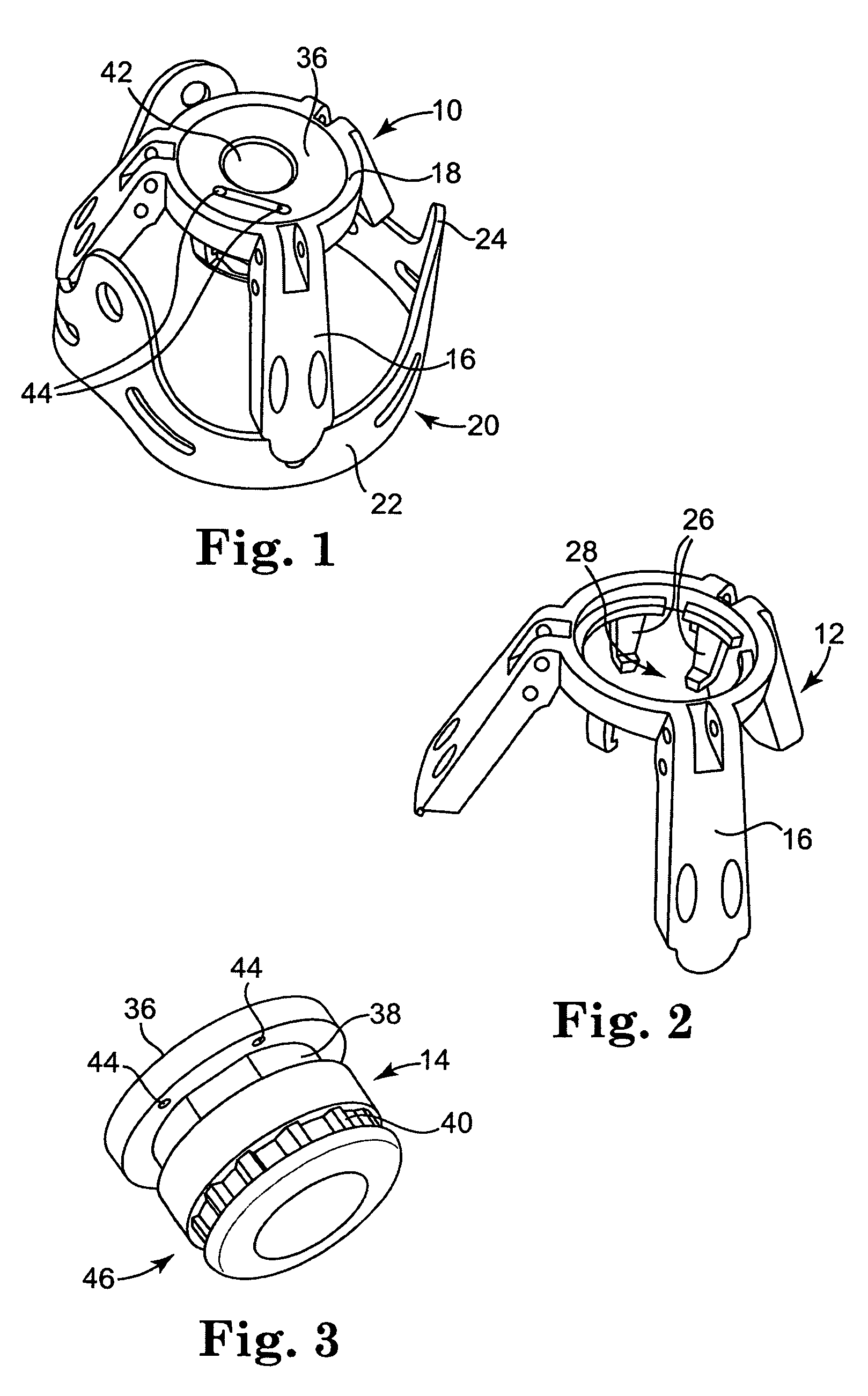
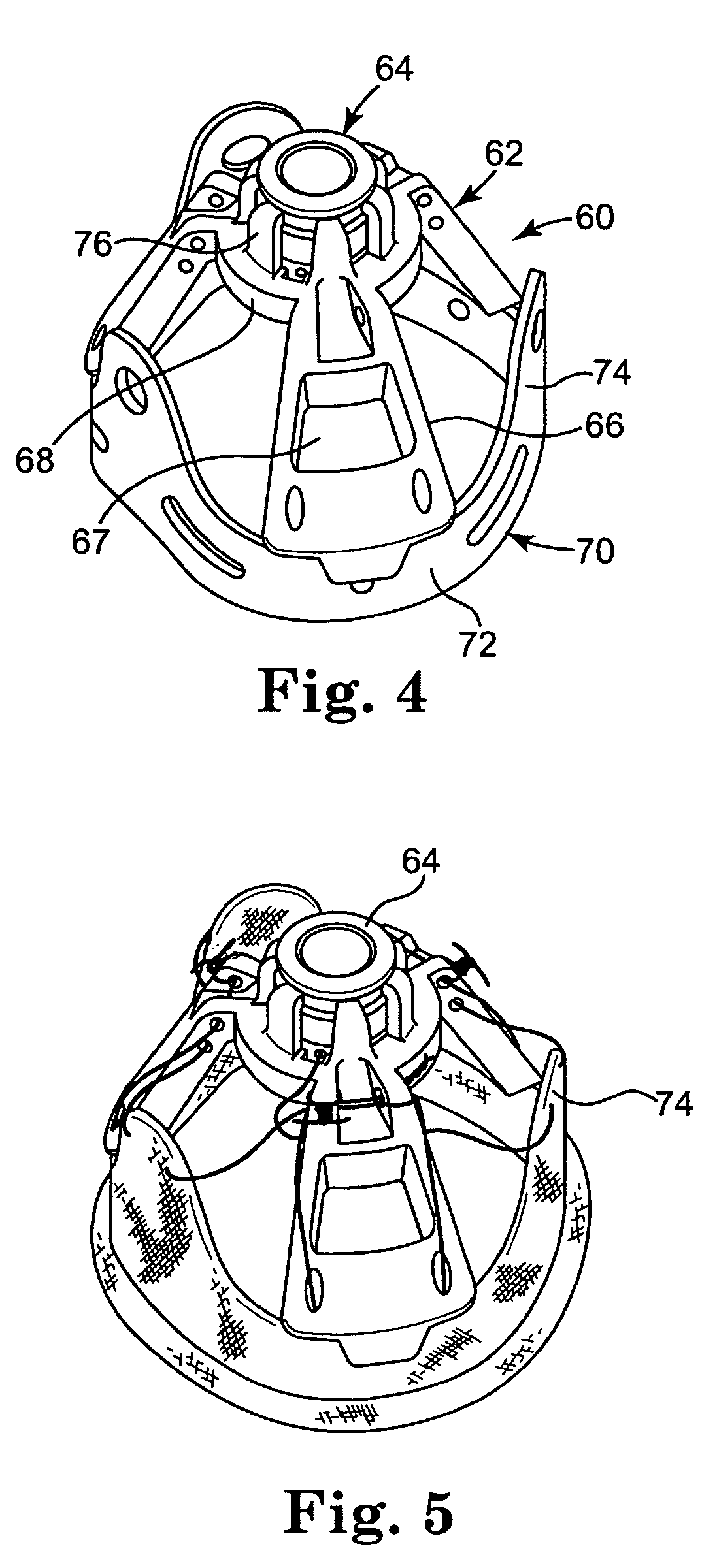
[0037]Referring now to the Figures, wherein the components are labeled with like numerals throughout the several Figures, and initially to FIGS. 1-3, one embodiment of a valve holder assembly 10 is illustrated, which generally includes a holder 12 and a rotor 14. Holder 12 includes three legs 16 extending from a base ring 18, where FIG. 1 shows the holder 12 positioned relative to a stent frame of an exemplary prosthetic heart valve 20, which may be an aortic valve, for example. Heart valve 20 includes a stent ring 22 from which three commissure posts 24 extend. For clarity of illustration, the cloth fabric and tissue material that make up the valve portion of the assembly (including the leaflets of the valve) are not shown in these figures. Each of the three legs 16 of the holder 12 are shown as positioned with their distal ends on the stent ring 22 between two adjacent commissure posts 24.

[0038]The holder 12 further includes three snap-fit fingers 26 that extend downwardly from th...


PUM


Abstract

A valve holder assembly for delivering a prosthetic heart valve having a stent base an multiple extending commissure posts. The valve holder assembly includes a holder and a rotor that is rotatable relative to the holder.

Description

CROSS-REFERENCE TO RELATED APPLICATIONS[0001]The present application claims priority to U.S. Patent Application No. 60 / 994,063, filed Sep. 17, 2007, and titled “HEART VALVE HOLDER FOR USE IN VALVE IMPLANTATION PROCEDURES”, the entire contents of which is incorporated herein by reference in its entirety.TECHNICAL FIELD[0002]The present invention relates generally to implantable valvular prostheses, and more particularly relates to a holding system or mechanism that can provide temporary prosthetic heart valve stent post deflection during implantation of valvular prostheses.BACKGROUND OF THE INVENTION[0003]Various types and configurations of prosthetic heart valves are used to replace diseased natural human heart valves. The actual shape and configuration of any particular prosthetic heart valve is dependent to some extent upon the valve being replaced (i.e., mitral valve, tricuspid valve, aortic valve, and pulmonary valve). In general terms, however, most prosthetic heart valve desig...

Claims


Application Information

Patent Timeline
Patent Type & Authority Patents(United States)
IPC IPC(8): A61F2/24
CPCA61F2/2427A61F2/243
Inventor BERGIN, CATHLEEN A.
Owner MEDTRONIC INC
Why Eureka
Try Eureka