Composite writer shield for improving writer performance

a writer and shield technology, applied in the field of composite shields, can solve the problems of reducing limiting the reader spacing, so as to improve the writing current saturation speed, improve the writing speed, and improve the writing speed

Active Publication Date: 2012-09-25
HEADWAY TECH INC
View PDF20 Cites 13 Cited by
  • Summary
  • Abstract
  • Description
  • Claims
  • Application Information

AI Technical Summary

Benefits of technology

[0015]One objective of the present invention is to provide a pp3 section of a main shield structure in a PMR write head with a configuration and composition that yields improved performance compared with a single magnetic layer that is optimized for magnetic performance (for example, a 19 kG material), or a single magnetic layer that is more optimal for mechanical performance but with compromised magnetic performance (for example, a 24 kG material with lower CTE).
[0016]Another objective of the present invention is to provide a pp3 section of a main shield structure according to the first objective that is readily implemented in manufacturing with a minimum number of changes in the fabrication process.

Problems solved by technology

A lower gamma ratio means the writer protrusion rate is much higher than the reader protrusion rate, and could potentially put a greater limit to achievable reader spacing.
On the other hand, the high moment alloy has less desirable magnetic performance which leads to poorer write current saturation speed.

Method used


Image

  • Composite writer shield for improving writer performance
  • Composite writer shield for improving writer performance
  • Composite writer shield for improving writer performance

Examples


second embodiment

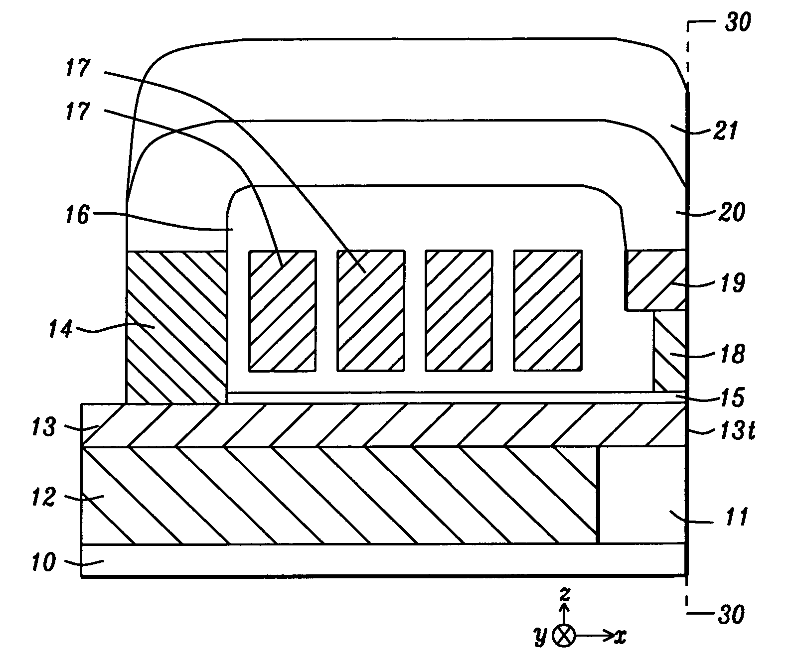
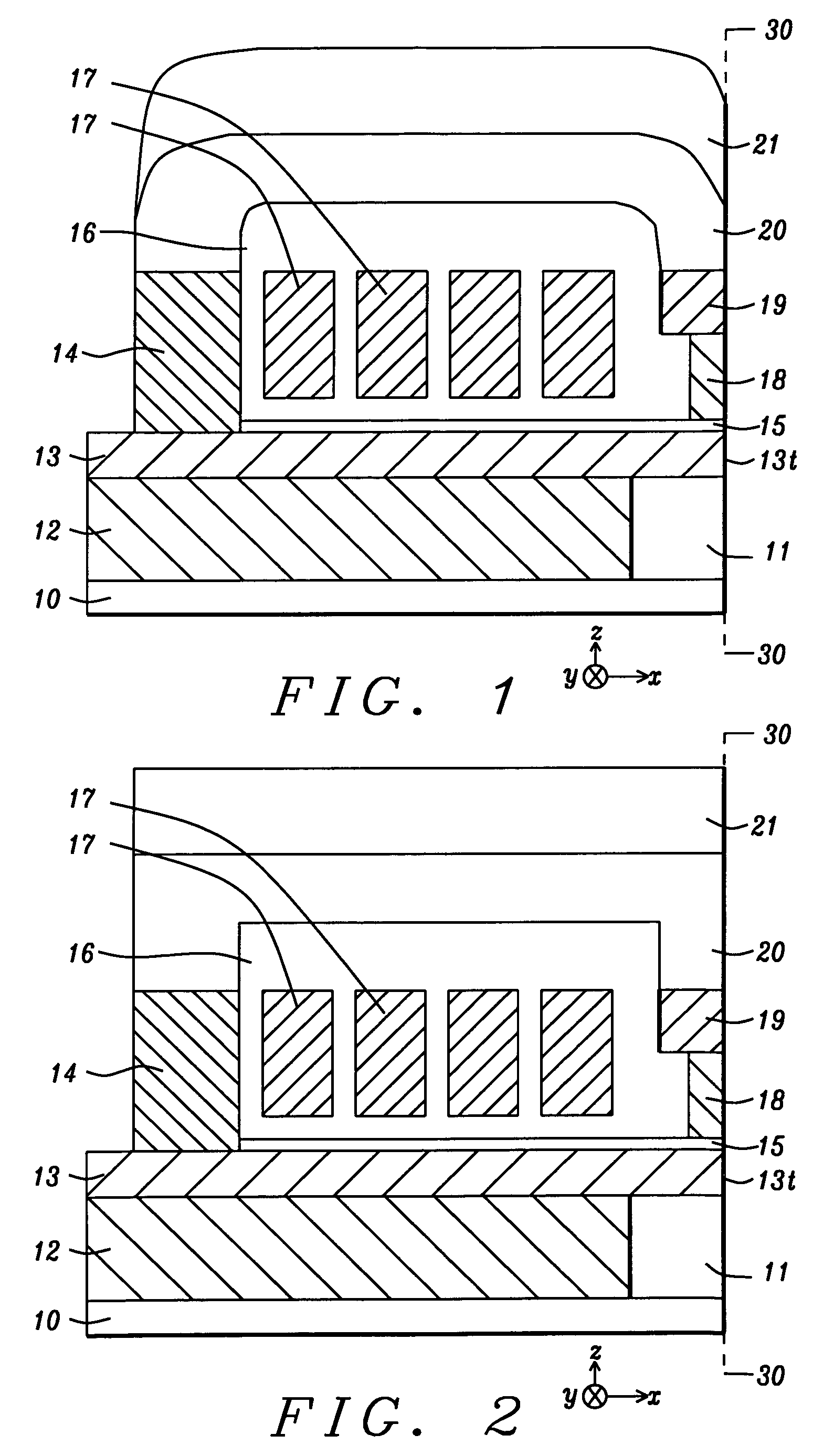
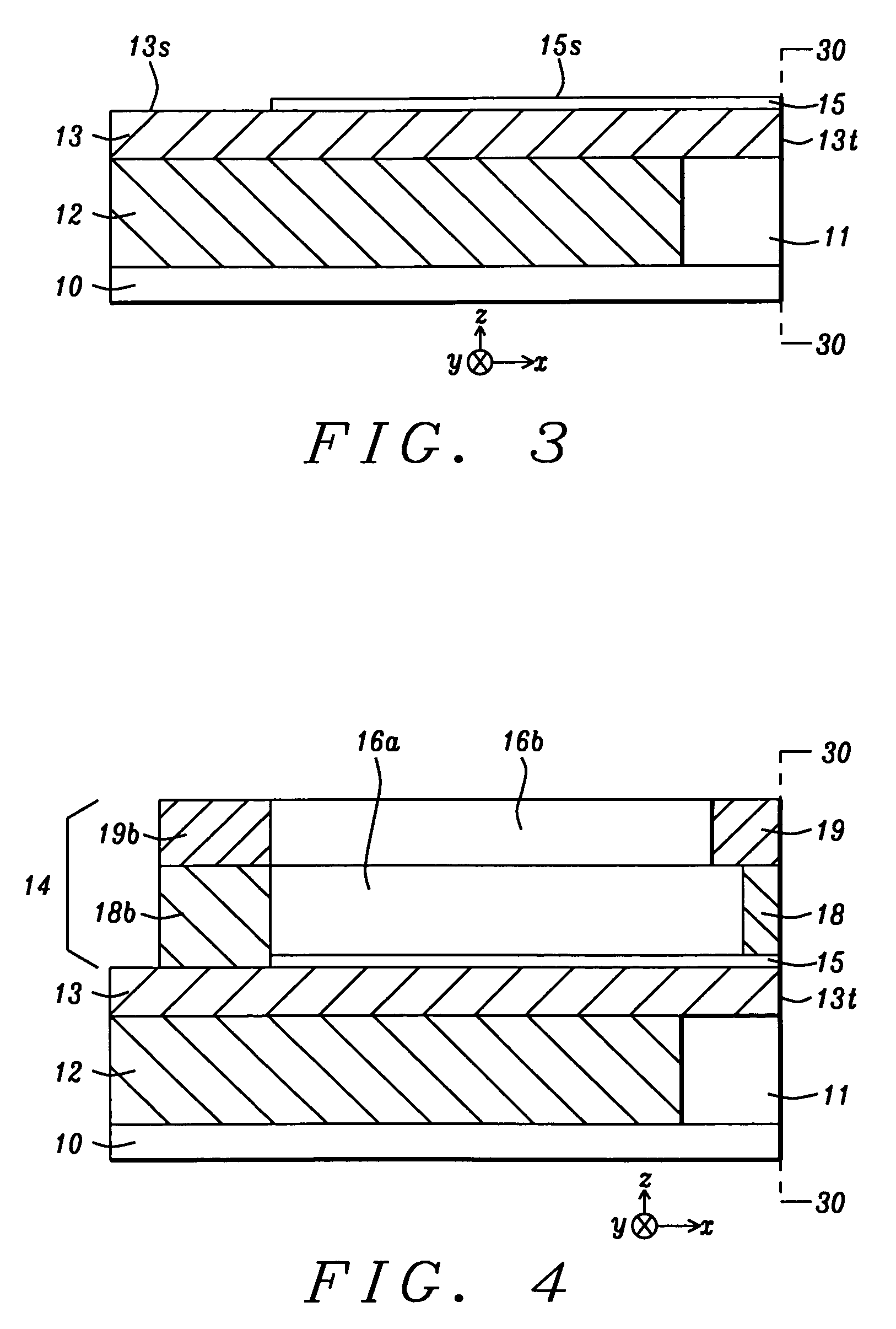
[0027]First a method of forming the PMR writer according to the present invention will be described. Referring to FIG. 3, a cross-sectional view is shown from a plane that is perpendicular to an air bearing surface (ABS) 30-30. There is a substrate 10 that may be a separation layer made of Al2O3 between a read head (not shown) and the PMR write head as described herein and shown in its entirety in FIGS. 1-2. The embodiment illustrated in FIG. 1 includes an arched shape for the upper shield section comprised of a lower layer 20, and upper layer 21 where lower layer is defined as the layer that connects with a second write shield and is closer to the main pole layer 13. A second embodiment in FIG. 2 shows an upper shield section with lower layer 20, and upper layer 21 that have essentially planar top surfaces opposite the main pole layer 13. It should be understood that the substrate 10 may be part of a slider (not shown) formed in an array of sliders on a wafer. After the PMR write h...

first embodiment

[0028]Returning to FIG. 3, a first embodiment is depicted wherein an etch stop layer (not shown) such as Ru may be deposited on the substrate 10. A first insulation layer 11 is deposited on the etch stop layer by a physical vapor deposition (PVD) or chemical vapor deposition (CVD) method. An opening (not shown) corresponding to the shape of the bottom yoke is formed in the first insulation layer 11 by conventional photoresist patterning and etching steps. After the patterned photoresist layer is stripped, a seed layer (not shown) may be deposited in the opening. Thereafter, the bottom yoke 12 may be formed by an electroplating method and is made coplanar with the first insulation layer by a chemical mechanical polish (CMP) step. The main pole layer 13 including pole tip 13t at the ABS 30-30 may be formed in a similar fashion by depositing a second insulation layer (not shown) on the first insulation layer 11 and bottom yoke 12 followed by forming an opening in the second insulation ...


PUM

PropertyMeasurementUnit
thicknessaaaaaaaaaa
thicknessaaaaaaaaaa
thicknessaaaaaaaaaa

Abstract

A PMR writer in a read / write head is disclosed wherein an upper shield covering the coil layer is comprised of a magnetic layer optimized for magnetic performance and a second layer used for tuning mechanical protrusion. The composite layer simultaneously provides high saturation magnetization and high permeability from the magnetic layer and low CTE from the second layer which tunes the relative spacing between the writer, reader, and the rest of the slider. In one embodiment, first and second write shields are formed on a write gap layer and have front portions at the ABS and back portions in a back gap region. The upper write shield connects on one side with the second write shield at the ABS and on a second side with the back gap region. This design can yield better reader and writer spacing for the same physical clearance which enables products with higher recording density.

Description

RELATED PATENT APPLICATION[0001]This application is related to the following: Ser. No. 10 / 886,284, filing date Jul. 7, 2004; which is assigned to a common assignee and is herein incorporated by reference in its entirety.FIELD OF THE INVENTION[0002]The invention relates to a composite shield in a perpendicular magnetic recording head (PMR) and a method for making the same. The design features a write shield layer comprised of a magnetic alloy optimized for magnetic performance above the coil layer and a second write shield layer made of a material with a low coefficient of thermal expansion (CTE) to optimize the mechanical performance related to the control of reader and writer spacing.BACKGROUND OF THE INVENTION[0003]Perpendicular recording has been developed in part to achieve higher recording density than is realized with longitudinal recording devices. A PMR write head typically has a main pole layer with a small surface area at an air bearing surface (ABS) and coils that conduct...

Claims


Application Information

Patent Timeline
Patent Type & Authority Patents(United States)
IPC IPC(8): G11B5/147
CPCG11B5/11G11B5/1278G11B5/3136G11B5/3146
Inventor WU, YANLIU, KOWANG
Owner HEADWAY TECH INC
Why Eureka
Try Eureka