Collision cell

a collision cell and cell technology, applied in the field of collision cells, can solve the problems of high rate at which ions are ejected from the collision cell once trapped, in the reverse direction, and in the backward direction, and achieve the effects of increasing the injection energy, easy electron giving, and reliable ra

Active Publication Date: 2012-10-02
THERMO FISHER SCI BREMEN
View PDF26 Cites 6 Cited by
  • Summary
  • Abstract
  • Description
  • Claims
  • Application Information

AI Technical Summary

Benefits of technology

[0013]The unwanted trapping of ions in field irregularities is mass dependent and more pronounced for ions with higher mass. This also means that, at a given mass to charge ratio, ions of higher charge (and thus higher mass) tend to be involuntarily trapped in the collision cell more easily. As a result, the invention provides particular improvement in the analysis of higher oligomers and polymers, such as for example peptides with more than 20 amino acids or proteins. This mechanism further reduces the ion ejection rate.
[0042]In the preferred embodiment, the ions of the first set have a negative charge. It is desirable to transmit negative ions through the collision cell unaffected without having to change the pressure in the collision cell. These ions tend to be more labile than positive ions and therefore the use of high potentials is not recommended. The standard method for overcoming irregularities of the potential in the collision cell (or in this case, transmission cell) is increasing the injection energy. However, this would result in significant loss of negative ions. In particular, ETD anions are specifically designed to give their electron away very easily. This means that these ions could also very easily be stripped in the collision cell, even at moderate energies (such as less than 10 eV). The method of the present invention advantageously addresses this difficulty.

Problems solved by technology

Ejection of the ions in a backwards direction is therefore problematic.
However, it has been found for existing arrangements that provide an axial gradient that the rate at which ions are ejected from the collision cell once trapped, or in the reverse direction, is much lower than would be expected.

Method used


Image

  • Collision cell
  • Collision cell
  • Collision cell

Examples


Embodiment Construction

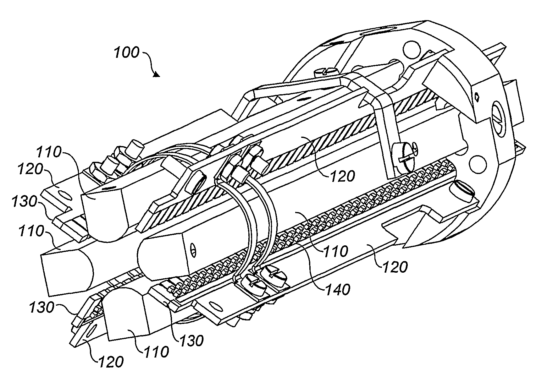
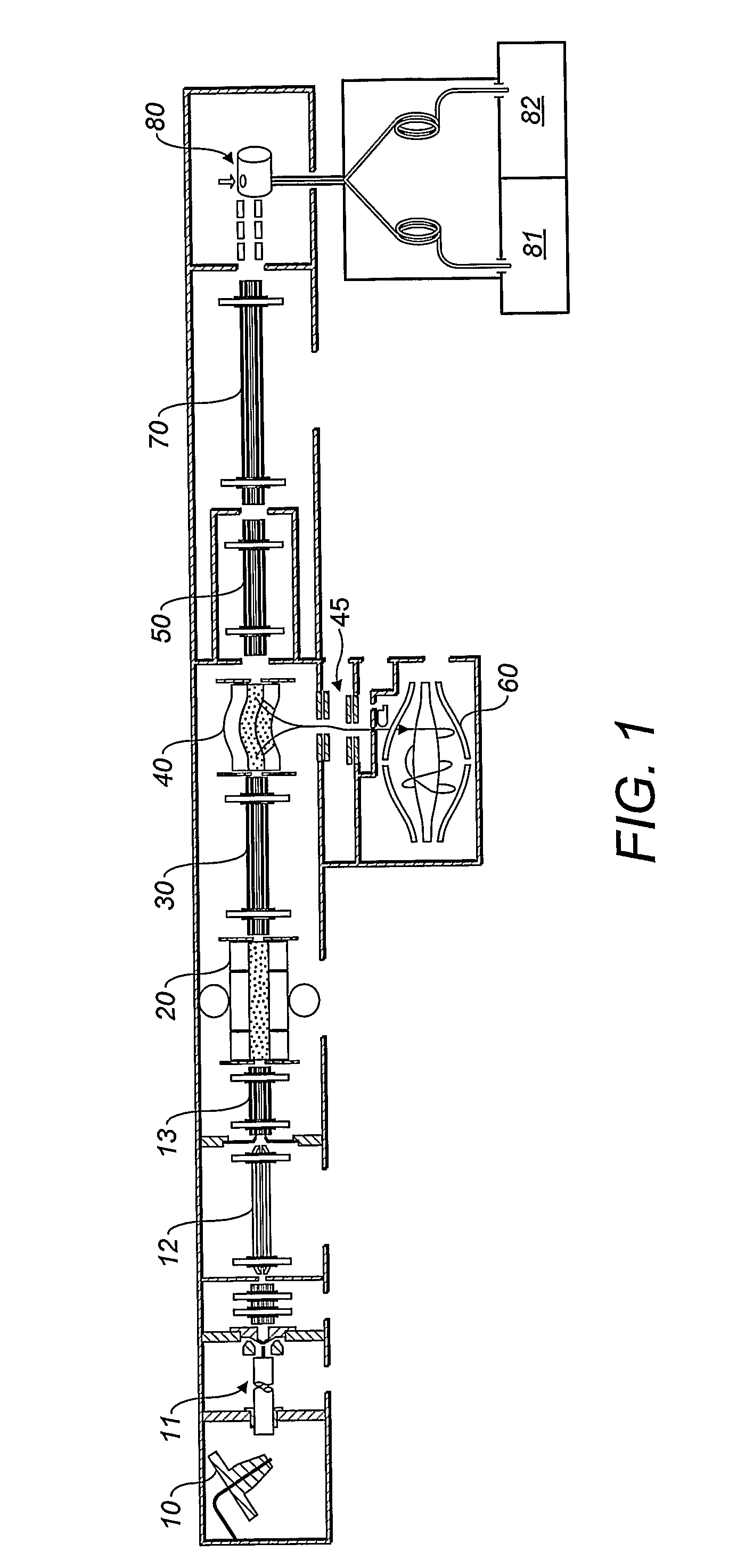
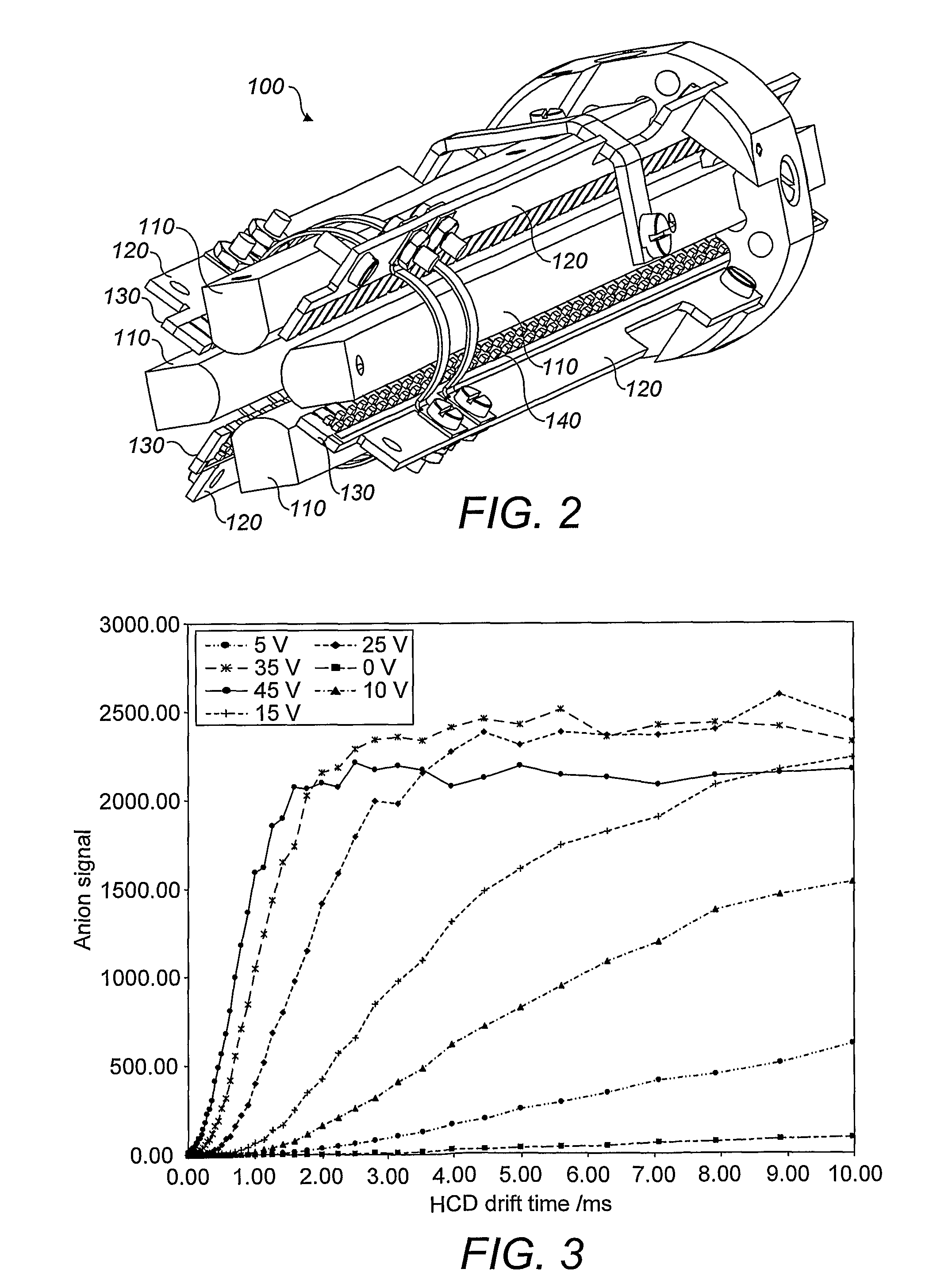
[0062]Referring first to FIG. 1, there is shown an overview of a known mass spectrometer, comprising: an ion source 10; a linear ion trap 20; a transfer multipole ion guide 30; a curved ion trap 40; a High-energy Collision Dissociation (HCD) collision cell 50; a mass analyser 60; a transfer multipole ion guide 70; and a reagent ion source 80.

[0063]Ions are generated in the ion source 10, and ejected towards ion introduction hardware 11, comprising heated capillary, skimmer and lenses. The ions are then guided through multipole ion guide 12 and multipole ion guide 13 to a Linear Ion Trap mass spectrometer 20, which can act as both a mass analyzer and an ion trap. Ions are ejected from the linear ion trap 20 to a transfer multipole ion guide 30, which acts as a quadrupole mass filter and which transfers the ions to a curved trap 40. Vertically below the curved trap 40 is a z-lens 45 and a mass analyser 60, which is this embodiment is an Orbitrap™ mass analyser.

[0064]To the right of th...


PUM


Abstract

A method of operating a gas-filled collision cell in a mass spectrometer is provided. The collision cell has a longitudinal axis. Ions are caused to enter the collision cell. A trapping field is generated within the collision cell so as to trap the ions within a trapping volume of the collision cell, the trapping volume being defined by the trapping field and extending along the longitudinal axis. Trapped ions are processed in the collision cell and a DC potential gradient is provided, using an electrode arrangement, resulting in a non-zero electric field at all points along the axial length of the trapping volume so as to cause processed ions to exit the collision cell. The electric field along the axial length of the trapping volume has a standard deviation that is no greater than its mean value.

Description

TECHNICAL FIELD OF THE INVENTION[0001]The invention relates to a collision cell and a method of operating a collision cell in a mass spectrometer. It also relates to a method of effecting electron transfer dissociation using a collision cell.BACKGROUND TO THE INVENTION[0002]In a mass spectrometer, a collision cell can be used for a variety of purposes. For instance, a collision cell can be used to reduce the thermal energy of ions, to permit more accurate mass analysis thereby.[0003]Collision cells can also be used in tandem mass spectrometry. In such techniques, structural elucidation of ionised molecules is performed by using a mass spectrum produced in a first mass analysis step, then selecting a desired precursor ion or ions from the mass spectrum, ejecting the chosen precursor ions (or ion) to a collision cell where they are fragmented, and transporting the ions, including the fragmented ions, to a mass analyser for a second mass analysis step in which a mass spectrum of the fr...

Claims


Application Information

Patent Timeline
Patent Type & Authority Patents(United States)
IPC IPC(8): H01J49/40
CPCH01J49/0045H01J49/26H01J49/06H01J49/0072H01J49/40H01J49/4225H01J49/0031H01J49/0481H01J49/0081H01J49/0422
Inventor MAKAROV, ALEXANDER A.DENISOV, EDUARD V.BALSCHUN, WILKONOLTING, DIRKGRIEP-RAMING, JENS
Owner THERMO FISHER SCI BREMEN
Why Eureka
Try Eureka