Gate level reconfigurable magnetic logic
a magnetic logic and gate technology, applied in the field of reprogrammable logic, can solve the problems of affecting the operation of the gate, and consuming a large amount of power, and achieve the effects of reducing the write current, and increasing the current density
- Summary
- Abstract
- Description
- Claims
- Application Information
AI Technical Summary
Benefits of technology
Problems solved by technology
Method used
Image
Examples
example 1
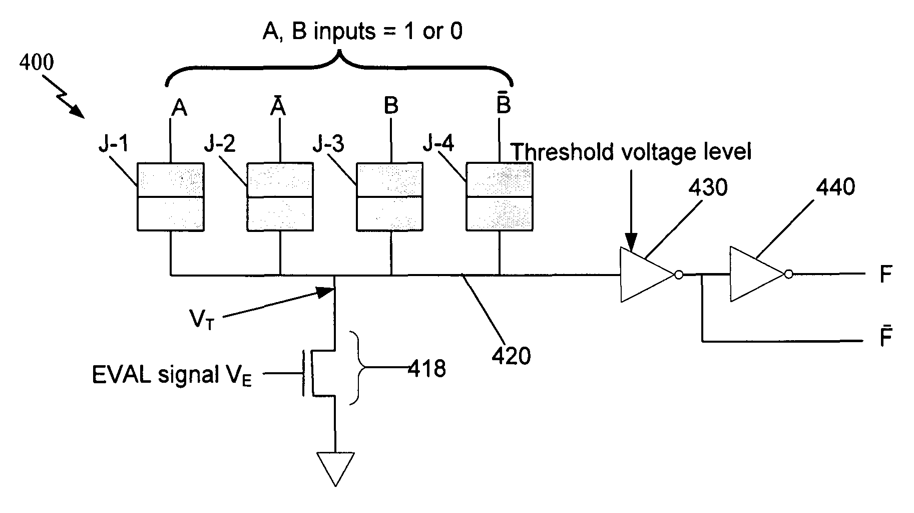
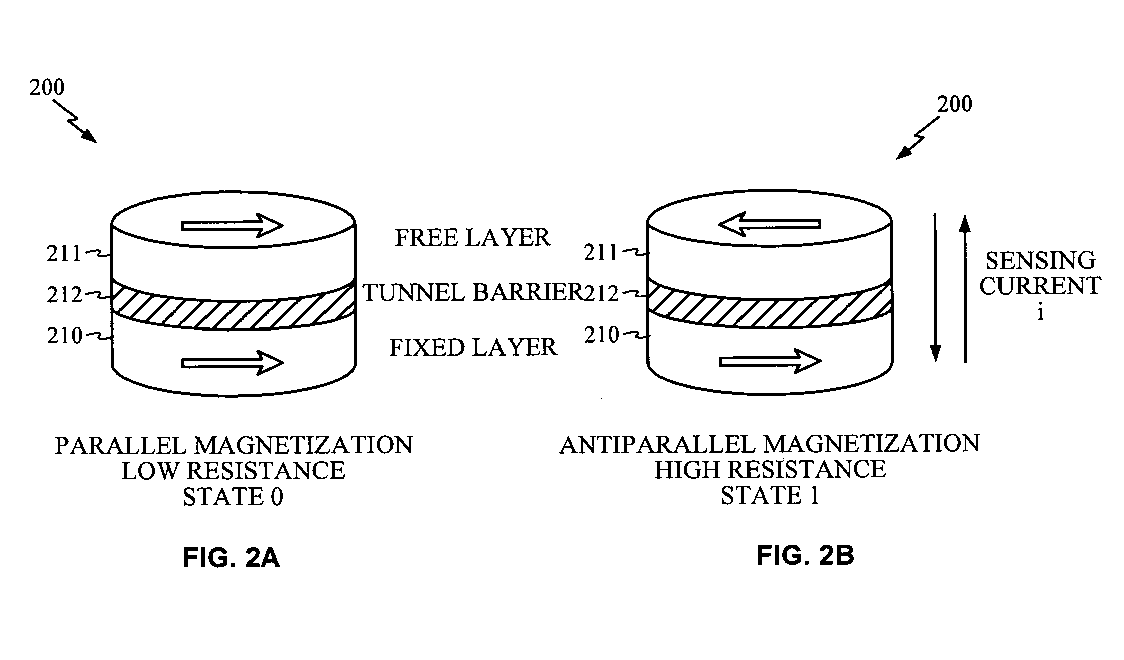
[0047]Assume the MTJ junctions J1-J4 are set to the states [1,0,1,0]. Therefore, the corresponding resistances are RJ-1(1)=5R0, RJ-2(0)=R0, RJ-3(1)=5R0, and RJ-4(0)=R0. For all four possible combinations of A,B and the resulting four input voltages [A, _A, B, _B] of magnitude VDD the measured voltage VT are shown in Table I.
[0048]
TABLE 1Transistor voltage VT for junction states [1, 0, 1, 0] versus inputs A, BAA—BB—VT / VDD10100.1810010.4201100.4201010.67
[0049]FIG. 5A is a representative plot of voltage output VT(A,B) for the possible combinations of inputs shown in Table 1, given that the state settings for the four STT MTJ junctions J-1 to J-4 are [1,0,1,0]. The output voltage may be indexed relative to the input states A,B, i.e., as VT(A,B). Inverter 420 receives the voltage VT(A,B) from summing line 420. Inverter 430 may be set to trigger an output if VT(A,B) exceeds the a threshold voltage. Inverter 430 then may amplify the input to output a logical 1 or 0 level (e.g., VDD or 0) d...
example 2
[0054]Assume the MTJ junctions J-1 to J-4 are set to the states [0,1,0,1]. Therefore, the corresponding resistances are RJ-1(0)=R0, RJ-2(1)=5R0, RJ-3(0)=R0, and RJ-4(1)=5R0. Using the same analysis as above, FIG. 5C is a representative plot of voltage output VT(A,B) for the possible combinations of inputs, given that the state settings for the four STT MTJ junctions J-1 to J-4 are [0,1,0,1]. Note that VT(1,1) is the highest output, as compared to the first example, where VT(0,0) was highest. If inverter 430 is set to trigger between VT(1,1) and VT(1,0) and output VDD or 0 accordingly, the truth table in Table 4 results. It can be seen that F is identical to a logical AND, and F_ is identical to a logical NAND.
[0055]
TABLE 4Truth Table for junction states [0, 1, 0, 1] versus inputs A, B,Threshold voltage set between VT(1, 1) and VT(1, 0)ABFF—1110100101010001ANDNAND
[0056]Similarly, if inverter 430 is set to trigger based on a threshold voltage between VT(1,0) and VT(0,0), the input and...
PUM
 Abstract
Description
Claims
Application Information
 - R&D
- Intellectual Property
- Life Sciences
- Materials
- Tech Scout
- Unparalleled Data Quality
- Higher Quality Content
- 60% Fewer Hallucinations
Browse by: Latest US Patents, China's latest patents, Technical Efficacy Thesaurus, Application Domain, Technology Topic, Popular Technical Reports.
© 2025 PatSnap. All rights reserved.Legal|Privacy policy|Modern Slavery Act Transparency Statement|Sitemap|About US| Contact US: help@patsnap.com


