
FPGA simulated annealing accelerator

a technology of simulated annealing and accelerator, which is applied in the direction of instruments, multi-objective optimisation, cad techniques, etc., can solve the problems of imposing high nre (non-recurring engineering) costs, unable to adapt to algorithmic changes in the post-deploy/fabrication phase, and unable to achieve the flexibility of algorithmic changes, etc., to improve the probability of finding the best solution, reduce the temperature, and prolong the program execution

Inactive Publication Date: 2012-10-23
UTAH STATE UNIVERSITY
View PDF15 Cites 19 Cited by
  • Summary
  • Abstract
  • Description
  • Claims
  • Application Information

AI Technical Summary

Benefits of technology

The FPGA-based architecture significantly speeds up the iterative repair algorithm, achieving a 68-fold speedup over traditional processors and a 5.2-fold speedup over desktop PCs, while reducing computational time and resource utilization.

Problems solved by technology

While they offer post-fabrication flexibility through software programmability, the demand for on-board autonomy-enabling applications has pushed the envelope of computation, complexity far beyond the reach of these processors.
Application specific integrated circuits (ASICs), while being capable of meeting the computation demands of these algorithms, incur very high NRE (non-recurring engineering) costs and offer little to no flexibility for algorithmic changes in the post-deployment / fabrication phase.

Method used


Image

  • FPGA simulated annealing accelerator
  • FPGA simulated annealing accelerator
  • FPGA simulated annealing accelerator

Examples


Embodiment Construction

[0035]We disclose a unique hardware architecture, derived from an ANSI C implementation of iterative repair using simulated annealing. In this implementation for the working example, a solution is represented as a string of start times for events numbered 0 to 99 for a problem consisting of 100 events that need to be scheduled. Events have dependencies, meaning that certain events must complete before others can start. FIG. 3 depicts this event dependency graph. Each event utilizes one unit of one of four types of resources. There are four resources of each type.

[0036]The resource type associated with each event is designated by the shape of the event node in FIG. 3. Each event, takes one time step to complete. Additional input parameters are a maximum schedule length of 32 time steps, an initial temperature of 10,000, a cooling rate of 0.9999, and a termination threshold of 0.0001. This means that the schedule cannot exceed 32 time steps, the simulated annealing temperature starts ...


PUM


Abstract

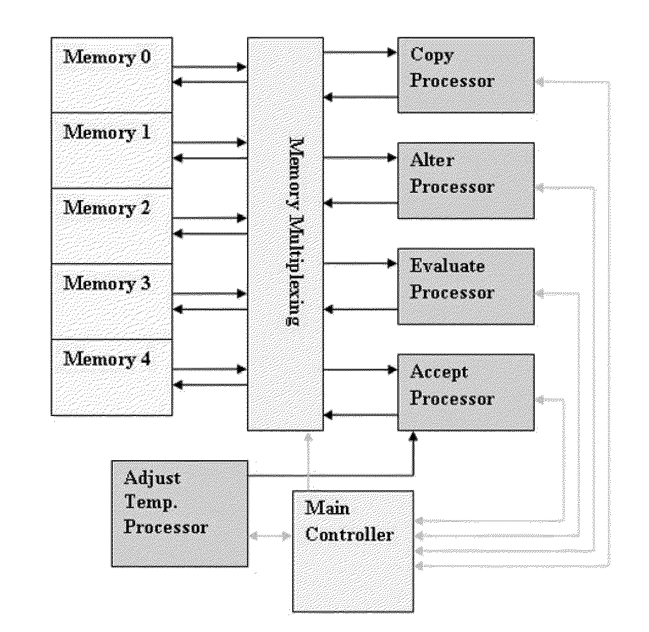
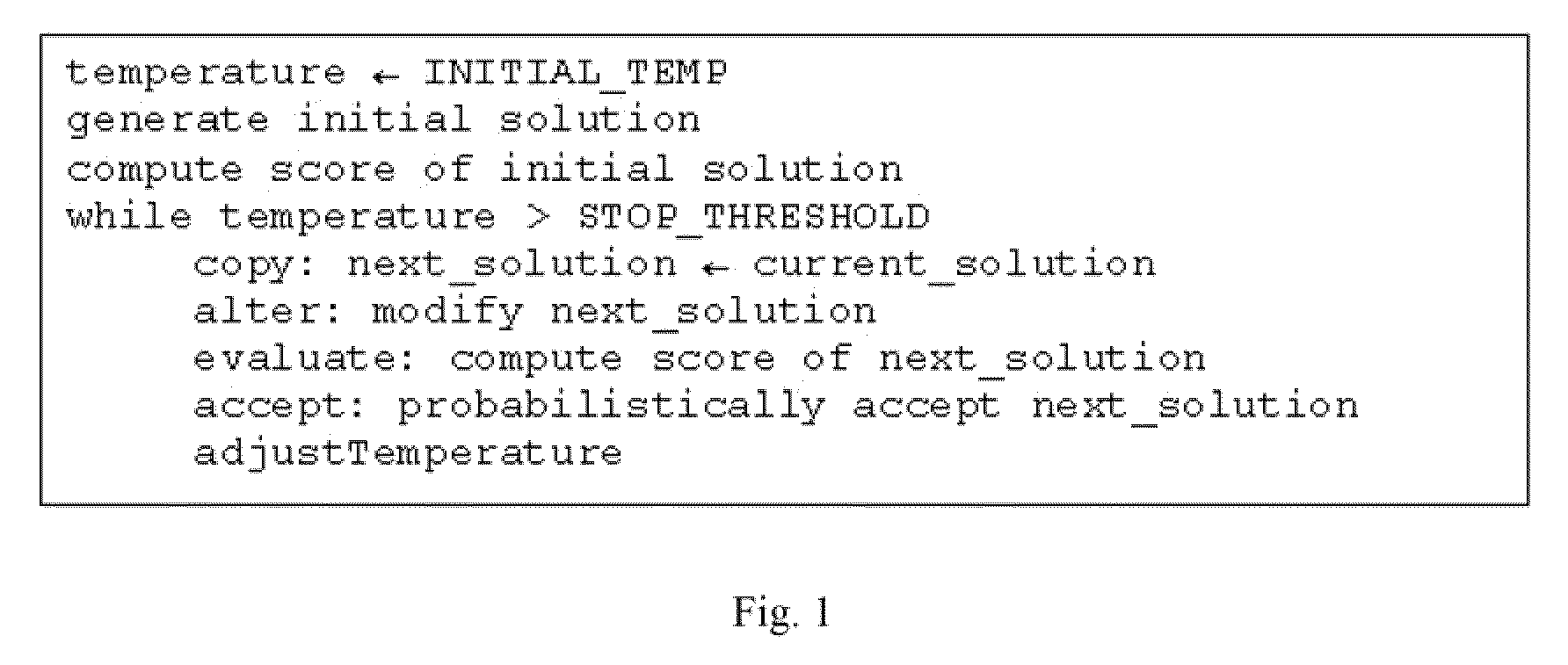
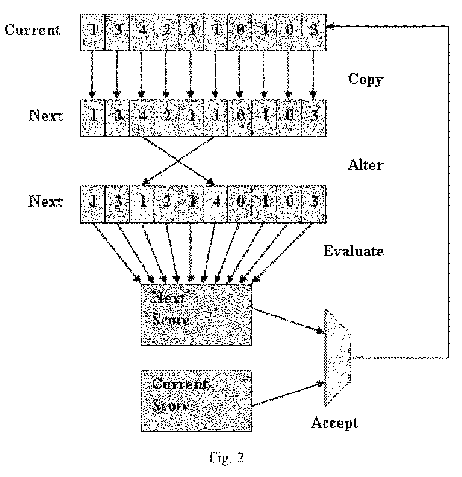
Iterative repair problems are generally solved using a combinatorial search method such as simulated annealing are addressed with a FPGA-based coarse-grain pipelined architecture to accelerate a simulated annealing based iterative repair-type event scheduling application. Over 99% of the work done by any simulated annealing algorithm is the repeated execution of three high-level steps: (1) generating, (2) evaluating, and (3) determining the acceptability of a new problem solution. A pipelined processor is designed to take advantage of these steps.

Description

RELATED APPLICATIONS[0001]This application claims priority to U.S. Provisional Application No. 61 / 074,225 filed on. Jun. 20, 2008, entitled “Architecture Template for Simulated Annealing Processor Derivation” and is incorporated herein by reference and claims priority to U.S. Provisional Application No. 61 / 155,637 filed on Feb. 26, 2009, entitled “FPGA Simulated Annealing Accelerator” and is incorporated herein by reference, and claims priority to U.S. Provisional Application No. 61 / 074,228 filed on Jun. 20, 2008, entitled “Method for Deriving an Efficient, Application-Specific, FPGA-Based Pipelines Processor”, and is incorporated herein by reference.TECHNICAL FIELD[0002]The present invention relates to methods and devices for controlling simulated annealing coding on field programmable gate arrays.BACKGROUND[0003]Microprocessors such as the PowerPC and x86 line have been the traditional work-horses of computing systems over the years. While they offer post-fabrication flexibility t...

Claims


Application Information

Patent Timeline
Patent Type & Authority Patents(United States)
IPC IPC(8): G06F17/50G06F9/455G06G7/48
CPCG06F17/5054G06F2217/08G06F2111/06G06F30/34
Inventor PHILLIPS, JONATHAN D.DASU, ARAVIND
Owner UTAH STATE UNIVERSITY
Learn More