DRAM memory cell having a vertical bipolar injector

a memory cell and injector technology, applied in semiconductor devices, digital storage, instruments, etc., can solve the problems of disturbance of neighbouring cells, difficulty in accurately controlling the voltage of the substrate serving as the base of the bipolar transistor, and disturbance of nearby memory cells, so as to reduce the surface area

Active Publication Date: 2012-11-06
SOITEC SA
View PDF112 Cites 25 Cited by
  • Summary
  • Abstract
  • Description
  • Claims
  • Application Information

AI Technical Summary

Benefits of technology

[0005]One technique for reducing the surface area occupied by such a floating body DRAM memory cell is described in the document US 2004 / 0108532. This document proposes creating a memory cell by associating a floating body horizontal FET transistor and a horizontal bipolar transistor suitable for injecting charges into the floating body. The low storage capacity of the floating body is thus increased. The horizontal bipolar transistor is more specifically arranged laterally to the FET transistor with the emitter (serving as injector) of the bipolar transistor formed in the substrate with a conductivity opposite to the latter, the base of the bipolar transistor being formed by the substrate and the collector of the bipolar transistor serving as floating body for the FET transistor.

Problems solved by technology

Besides the fact that this high voltage is likely to damage the cell, it can also disrupt the operation of nearby memory cells.
Moreover, this memory cell has the drawback that it is difficult to accurately control the voltage of the substrate serving as base for the bipolar transistor.
Since the injector is, moreover, shared between two adjacent memory cells, the result is a risk of disturbances between these neighbouring cells.
It will therefore be understood that the memory cell according to the document US 2004 / 0108532 is not totally satisfactory, and that there is still a need to remedy the abovementioned drawbacks in the prior art.

Method used


Image

  • DRAM memory cell having a vertical bipolar injector
  • DRAM memory cell having a vertical bipolar injector
  • DRAM memory cell having a vertical bipolar injector

Examples


Embodiment Construction

[0040]The preferred embodiments of the invention to be described do not limit the scope of the invention, since these embodiments are illustrations of several preferred aspects of the invention. Any equivalent embodiments are intended to be within the scope of this invention. Indeed, various modifications of the invention in addition to those shown and described herein, such as alternate useful combinations of the elements described, will become apparent to those skilled in the art from the subsequent description, and such modifications are also intended to fall within the scope of the appended claims.

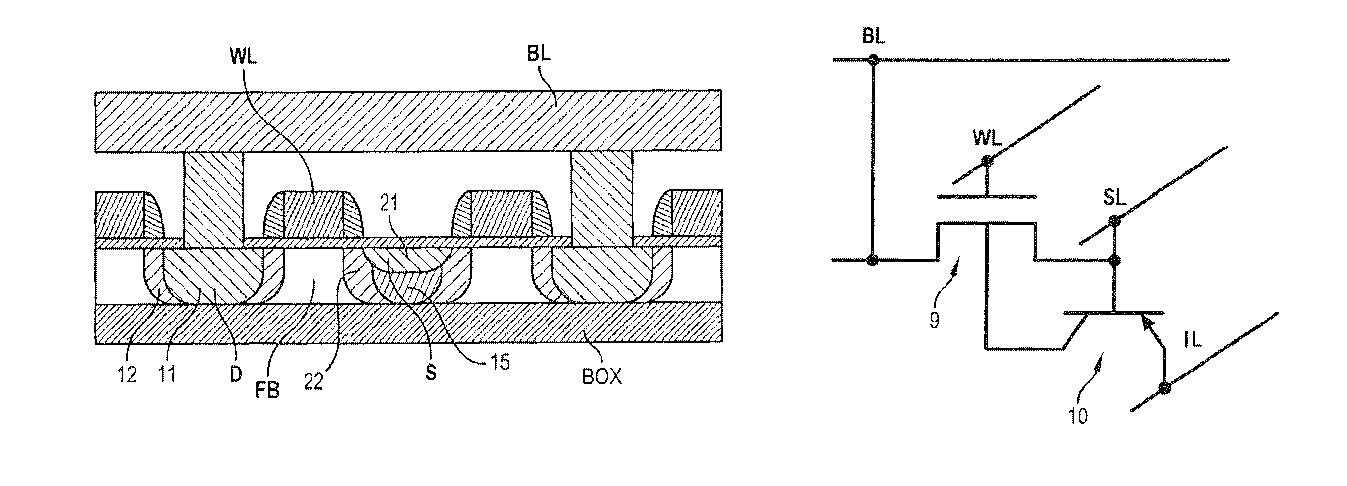
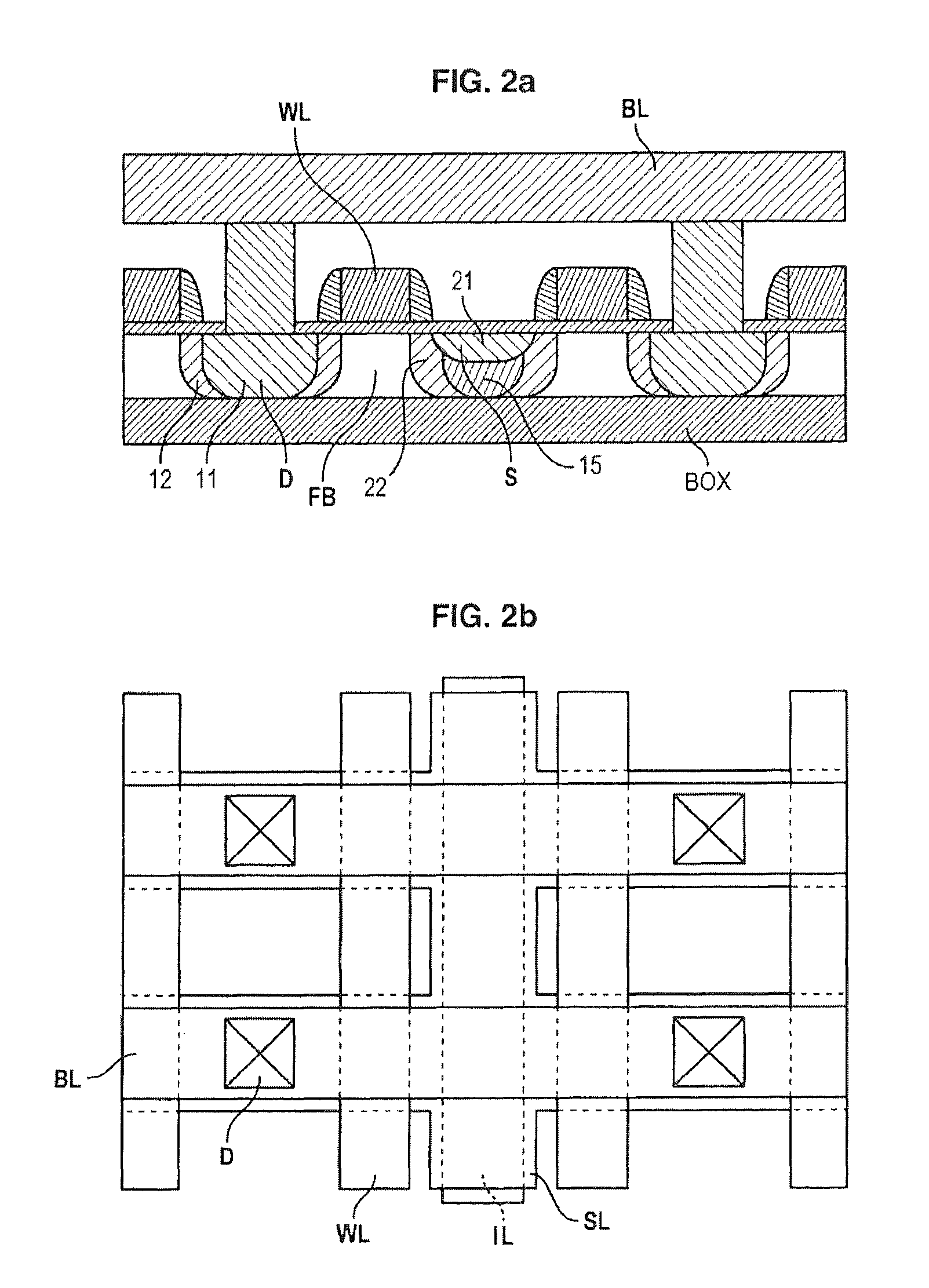
[0041]Referring now to FIG. 2a, a cross-sectional view of a memory cell according to a preferred embodiment of the first aspect of the invention is represented. This cell comprises an FET transistor having a source S, a drain D and a floating body FB between the source and the drain, and an injector that can be controlled to inject a charge into the floating body FB of the FET transist...


PUM


Abstract

The invention relates to a memory cell having an FET transistor with a source, a drain and a floating body between the source and the drain, and an injector that can be controlled to inject a charge into the floating body of the FET transistor. The injector includes a bipolar transistor having an emitter, a base and a collector formed by the body of the FET transistor. Specifically, in the memory cell, the emitter of the bipolar transistor is arranged so that the source of the FET transistor serves as the base for the bipolar transistor. The invention also includes a memory array comprising a plurality of memory cells according to the first aspect of the invention, and to methods of controlling such memory cells.

Description

FIELD OF THE INVENTION[0001]The field of the invention is that of semiconductor devices, and more particularly that of memory cells formed by a field effect transistor FET with floating body, and memory cell arrays comprising a plurality of memory cells of this type.BACKGROUND OF THE INVENTION[0002]FIG. 1 shows a cross-section of a conventional floating body DRAM (dynamic random access memory) memory cell. The conventional floating body DRAM cell is formed in a silicon-on-insulator (SOI) substrate comprising a thin film of silicon 3 separated from the base substrate 1 by a buried oxide layer (BOX) 2. A floating body 4, a source region 5 and a drain region 6 are formed in the thin film 3 on top of the BOX 2. A gate dielectric layer 7 and a gate electrode 8 are sequentially deposited on top of the floating body 4. The drain region 6 is connected to a bit line BL, the source region 5 is connected to a source line SL and the gate electrode 8 is connected to a word line WL.[0003]The floa...

Claims


Application Information

Patent Timeline
Patent Type & Authority Patents(United States)
IPC IPC(8): G11C11/40G11C11/402
CPCG11C11/404H01L27/0711H01L27/10802H01L29/086H01L29/7302H01L29/7841G11C2211/4016H10B12/20
Inventor MAZURE, CARLOSFERRANT, RICHARD
Owner SOITEC SA
Why Eureka
Try Eureka