Compact narrow band imaging system

a narrow band imaging and compact technology, applied in the field of narrow band imaging apparatus or systems, can solve the problems of small fires in the wilderness that can become forest fires, imaging sensors may be overwhelmed by daylight, and detection presents a much greater challenge, so as to reduce the size and weight of equipment, the effect of reducing the size and weigh

Inactive Publication Date: 2012-11-20
RODGERS WAYNE EUGENE +1
View PDF3 Cites 12 Cited by
  • Summary
  • Abstract
  • Description
  • Claims
  • Application Information

AI Technical Summary

Problems solved by technology

For example, small fires in the wilderness can become forest fires that spread to populated areas.
Anti-aircraft missiles sent aloft by burning rocket fuel when launched by terrorists or enemy combatants often target civilian and military aircraft.
However, during daytime hours the detection presents a much greater challenge.
This is because imaging sensors may be overwhelmed by daylight, including direct sunlight, sunlight scattered from the sky and clouds, and sunlight reflected from objects on the ground or in the air.
Daylight can also overwhelm imaging sensors used for viewing the health of crops, those used for LIDAR (Light Detection and Ranging), FLIR (Forward Looking InfraRed) systems, and laser communications receivers.
The IR detectors used in such applications are expensive.
Thus few private and commercial vehicles or aircraft are equipped with IR imaging threat detection systems.
In addition, processing IR images to determine what sources are of interest is complex.
The cost of these powerful processors adds to the cost of a system based on an IR detector.
The detectors and extensive processing lead to increased cost, size and weight of systems that rely on IR imagers.
The cold-cell MOFs, have a limited field-of-view, are bulky and need continuous calibration to guarantee long-term stability.
While prior implementations of the hot-cell MOF can have a moderate field-of-view, they are difficult to construct in a way that minimizes polarization-inducing stresses in the cell windows and oven enclosure windows.
Furthermore, the hot cell filters require bulky ovens to maintain cell temperature and control vapor density.
Thus, conventional MOF implementations have a limited usefulness for monitoring large sections of Earth or sky for fires, gunfire, missiles and other important combustion events.
Especially on aircraft, the total volume and weight available for a combustion monitoring system, such as a missile warning system, is limited.
A large array of narrow field of view cold cell MOFs, or hot-cell MOFs with bulky ovens are simply not feasible on an aircraft.
Optical losses encountered at these windows and within the external camera's optics are a factor in the system detection limits.
The housings for these detectors must incorporate thermal, environmental, and optical features that add weight, power consumption, size, and optical losses to the prior art MOF imaging system.
At the speeds required for threat detection even the signal delays caused by wire lead lengths between the detector and the signal processor can be significant.
However, because of arrangement and positioning of the components and other differences, this prior art apparatus does not offer many of the advantages of the present invention.

Method used


Image

  • Compact narrow band imaging system
  • Compact narrow band imaging system
  • Compact narrow band imaging system

Examples


Embodiment Construction

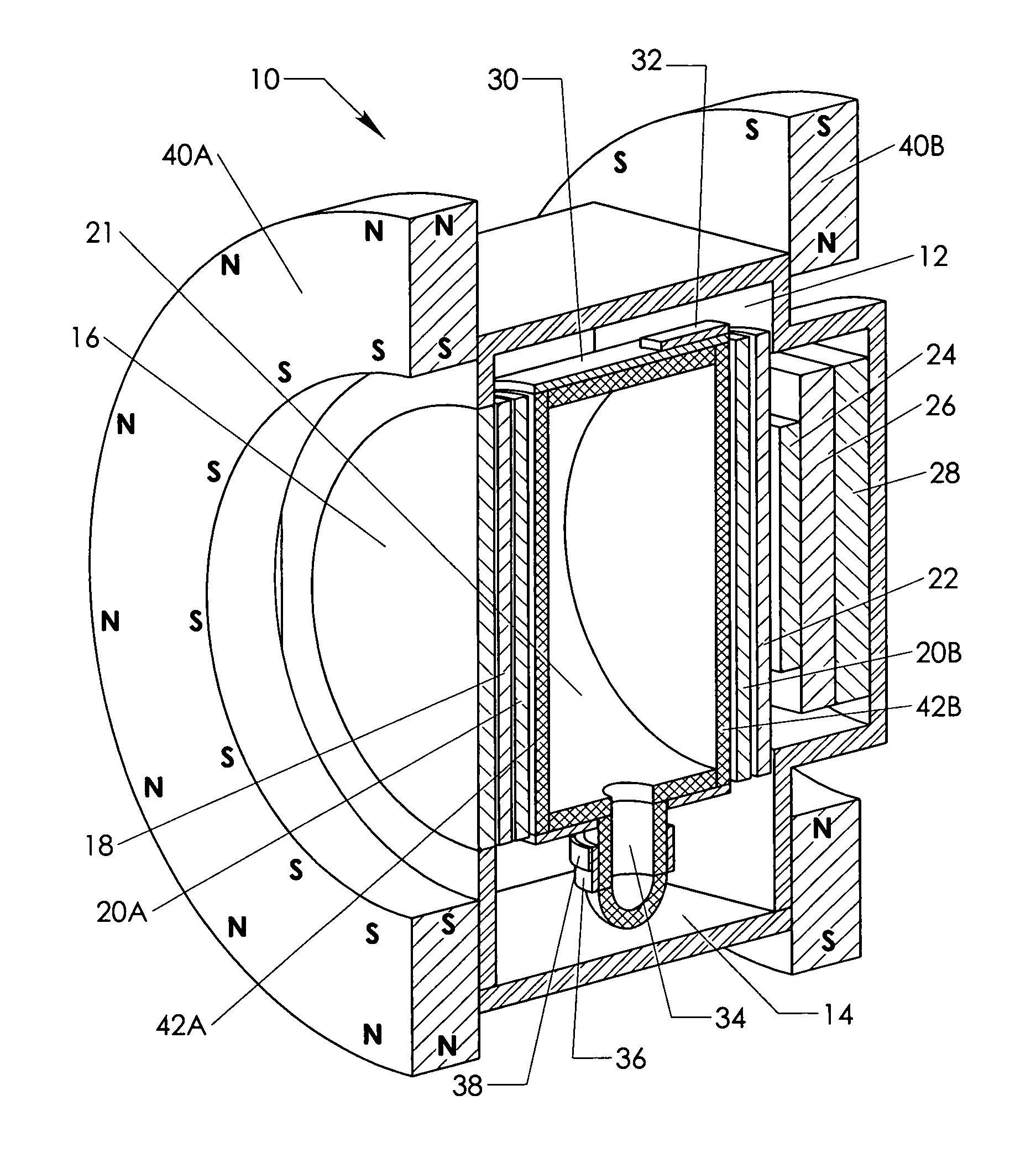
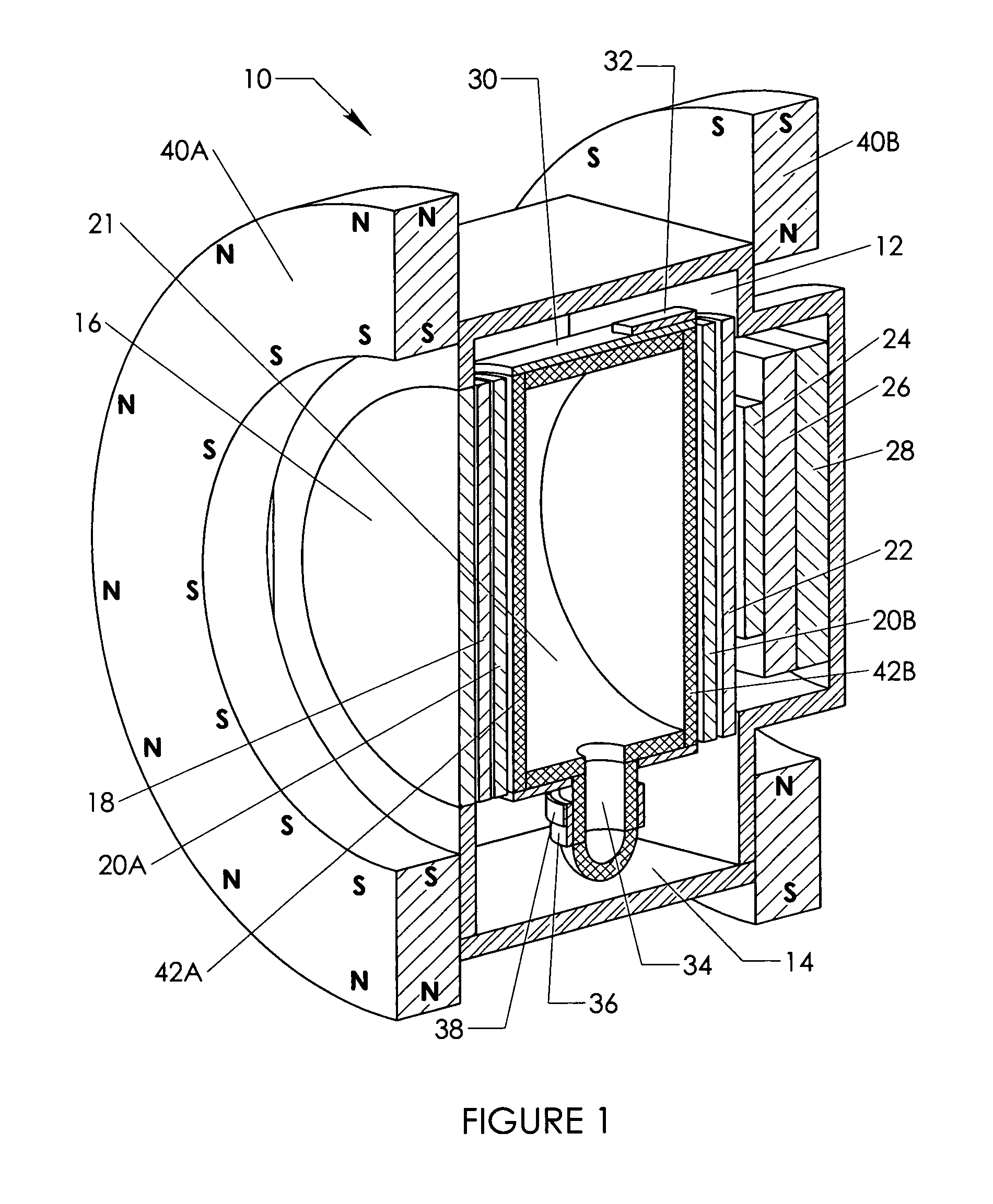
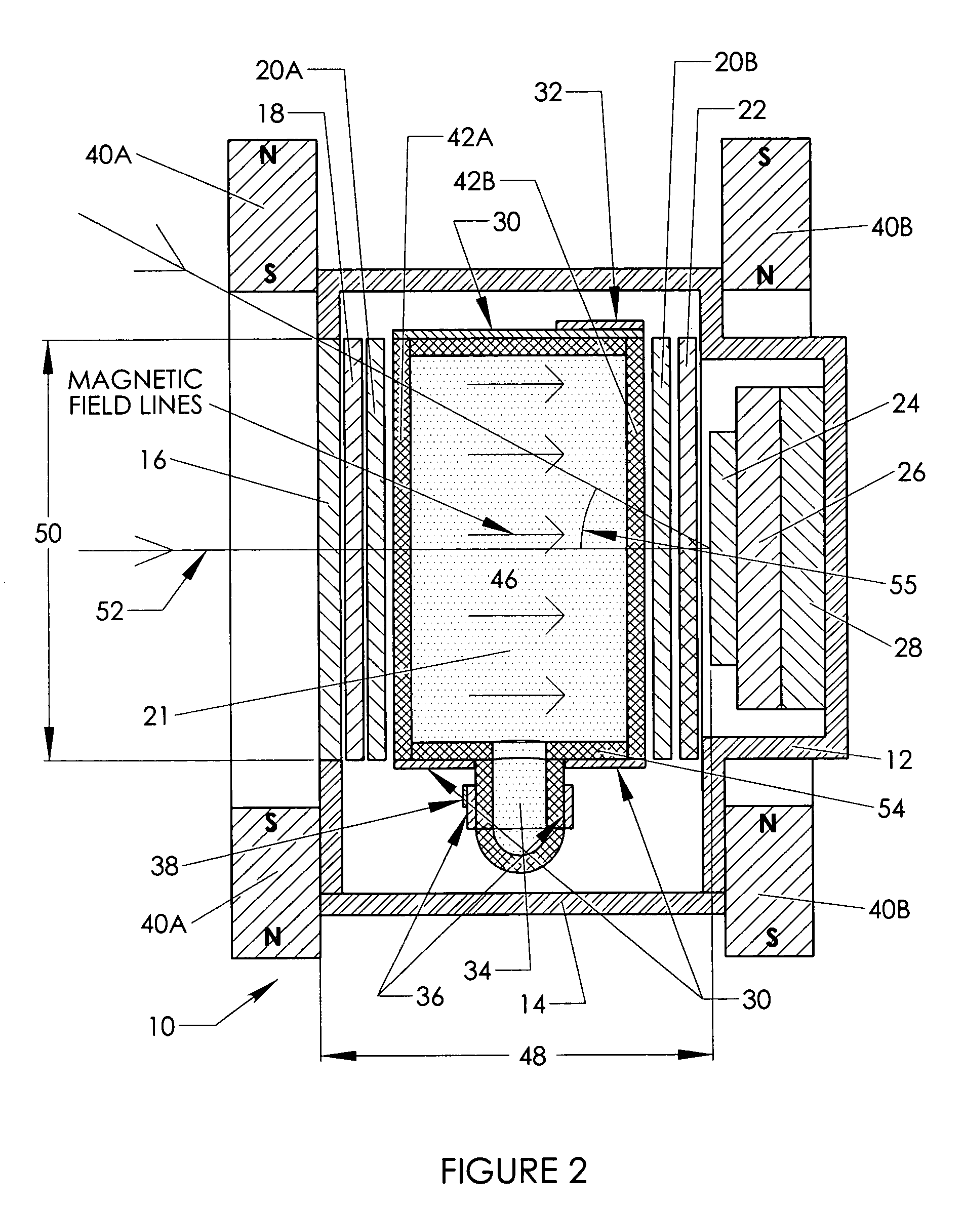
[0026]The following specification, taken in conjunction with the drawings, sets forth the general principles and the preferred embodiments of the present invention. The embodiments of the invention disclosed herein are the best modes contemplated by the inventor for carrying out his invention in a commercial environment, although it should be understood that various modifications can be accomplished within the parameters of the present invention.

[0027]The invention is best described by first describing the design parameters and requirements for the operating principles and components utilized in the several embodiments of the invention.

[0028]Some of the general principles and components are already described in the prior art, such as for example in United States Patent Application Publication No. 2007 / 0017281, published on Jan. 25, 2007, the specification of which is expressly incorporated herein by reference.

General Principles, Design Parameters

[0029]The operation of a narrow band ...


PUM


Abstract

A compact narrow band imaging system includes a vapor cell having a gas that receives and transmits light in accordance with the Faraday effect. A magnetic source is provided for applying a magnetic field to the vapor cell. Crossed polarizers are disposed before and after the vapor cell creating a Faraday optical filter. The only light that passes through the filter is light within a narrow band near the absorption peaks of the vapor. Other optical elements of the imaging system including filters, image detectors, electron multipliers, signal digitizers, and heat filters are co-located within the imaging system's common thermal isolation container to provide improved performance. The compact system is suitable for wide area surveillance, including daylight surveillance for combustion sources such as forest fires and missile exhaust.

Description

BACKGROUND OF THE INVENTION[0001]1. Field of the Invention[0002]The present invention relates to narrowband imaging apparatus or systems, and in particular to compact, light weight imaging apparatus or systems suitable for detecting from a mobile platform optical emissions from combustion in the presence of daylight.[0003]2. Brief Description of Prior Art[0004]Threats to human life and property are often harkened by combustion. For example, small fires in the wilderness can become forest fires that spread to populated areas. Anti-aircraft missiles sent aloft by burning rocket fuel when launched by terrorists or enemy combatants often target civilian and military aircraft. At night, such combustion sources are readily detected by the light emitted. However, during daytime hours the detection presents a much greater challenge. This is because imaging sensors may be overwhelmed by daylight, including direct sunlight, sunlight scattered from the sky and clouds, and sunlight reflected fr...

Claims


Application Information

Patent Timeline
Patent Type & Authority Patents(United States)
IPC IPC(8): G01R33/032G02B5/30
CPCG01R33/032G02B26/02
Inventor RODGERS, WAYNE EUGENERING, LAWRENCE SCOTT
Owner RODGERS WAYNE EUGENE
Why Eureka
Try Eureka