Tunable laser system

a laser system and tunable technology, applied in the direction of laser details, semiconductor lasers, instruments, etc., can solve the problems of inability to meet the requirements of optical telecom applications, inability to use tunable lasers employing moving parts, and inability to market penetration of tunable lasers, etc., to achieve easy assembly, reduce space, and achieve wavelength accuracy and stability

Inactive Publication Date: 2013-02-05
GAO PEILIANG
View PDF17 Cites 15 Cited by
  • Summary
  • Abstract
  • Description
  • Claims
  • Application Information

AI Technical Summary

Benefits of technology

[0007]A tunable laser cavity utilizes a frequency shift compensated acousto-optic tunable filter with single radio frequency (RF) transducer. The wavelength accuracy and stability is achieved by a wavelength locker utilizing two separate intracavity light beams without the need to use beam splitters to significantly reduce the space typically needed by a conventional wavelength locker, and provide more stable operation and easy assembly. By using different laser gain mediums, acoustic wave driving frequencies and acousto-optical crystals, this invention can be used to make tunable lasers in wide range of optical wavelengths and output powers.

Problems solved by technology

Unfortunately, market penetration of tunable lasers is inhibited by the limitations of existing tunable lasers in their compactness, wavelength tuning range, tuning speed and output power, etc.
Tuning techniques that rely on mechanical adjustment of the angle of a grating or prism, is very susceptible to the mechanical shock and vibration causing short term and long term performance instability, therefore tunable lasers employing moving parts are not suitable for optical telecom applications.
Thermal tuning is intrinsically slow, and therefore its applications are limited.
The key problems with the existing design of external cavity tunable laser utilizing acousto-optic filter for application in fiber optic telecom network are: (1) Doppler frequency shift compensation is usually achieved by two crystals, which makes alignment very difficult.
(2) two RF transducers bonded on the same crystal as disclosed in some US patens, which significantly increases the cost.

Method used


Image

  • Tunable laser system
  • Tunable laser system
  • Tunable laser system

Examples


Embodiment Construction

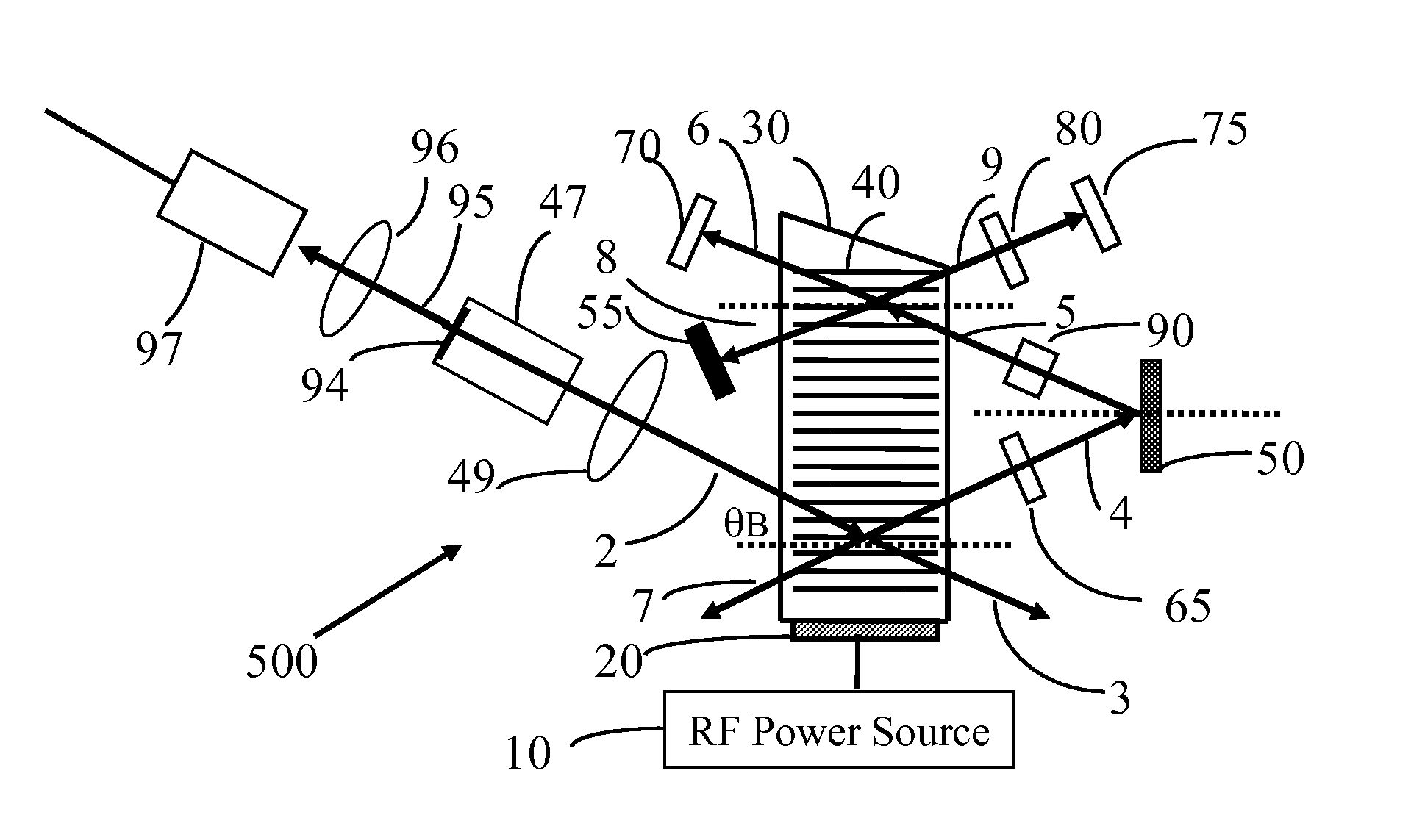
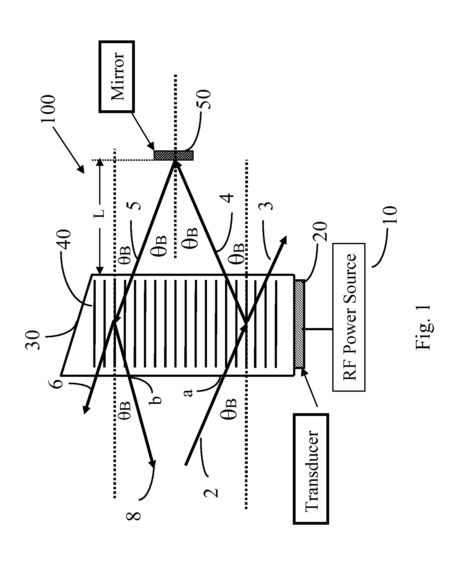
[0027]FIG. 1 shows, one embodiment of a compact, frequency-shift compensated, wavelength tunable optical filter. The embodiment 100 includes a medium 30, an acoustical transducer 20, and radio frequency (RF) power source 10, and an optical mirror 50.

[0028]There are two basic types of tunable acousto-optic filters, collinear type and noncollinear type. The noncollinear type includes the isotropic Bragg diffraction type and far-off-axis anisotropic Bragg diffraction type. The far-off-axis anisotropic Bragg diffraction has more practical value due to its narrow tuning bandwidth such as discussed in several U.S. patents.

[0029]In one embodiment, the medium 30 is anisotropic and birefrigent, such as when narrow band tuning is desired. One such material, TeO2, operating in shear mode has been used extensively for such applications due to its high optical homogeneity, low light absorption, and high optical power capability.

[0030]Other materials such LiNbO3, CaMoO4 and PbMoO4, are also used ...


PUM


Abstract

A tunable laser system utilizes a frequency shift compensated acousto-optic tunable filter. The wavelength accuracy and stability is achieved by a wavelength locker utilizing two separate intracavity light beams without the need to use beam splitters to significantly reduce the space typically needed by a conventional wavelength locker, and provide more stable operation and easy assembly. The acoustic optical tunable filter includes an acousto-optical crystal with a transducer coupled to the crystal to generate acoustic waves, and an optical mirror to reflect the diffracted light beam back to the acousto-optical medium again such that the frequency shift by two diffractions is compensated. By using different laser gain mediums, acoustic wave driving frequencies and acousto-optical crystals, this invention can be used to make tunable lasers in wide range of optical wavelengths for many different applications.

Description

BACKGROUND OF THE INVENTION[0001]The present invention relates to the apparatuses and method of wavelength tunable laser with wavelength locker and power monitor. More particularly, this invention relates to a laser resonant cavity implemented with wavelength shift compensated acousto-optic tunable filter and wavelength locker and power monitor design by which the fast tuning speed, stable wavelength and power performance can be realized.[0002]Most modern telecommunications systems are based on fiber optic transmission. The fiber optic networks offer both unprecedented capacity and the deployment flexibility needed to support a wide range of evolving and emerging broadband applications. Widely tunable lasers help to maximize existing fiber optic network resource. The ability to dynamically provision bandwidth provides the ability to move traffic from overcrowded channels to unused channels to meet the demands for Internet access. Tunable laser is also a key prerequisite as networks ...

Claims


Application Information

Patent Timeline
Patent Type & Authority Patents(United States)
IPC IPC(8): H01S3/117
CPCH01S5/0687H01S5/141H01S3/1068
Inventor GAO, PEILIANG
Owner GAO PEILIANG
Why Eureka
Try Eureka