
Optical fibre sensor assembly

a technology of optical fibre and sensor, applied in the direction of optical detection, acceleration measurement using interia force, transmission system, etc., can solve the problems of limited technique and limited number of sensors that can be multiplexed, and achieve the effect of effective air backing, simple manufacturing, and good noise performan

Inactive Publication Date: 2013-02-05
OPTASENSE HLDG LTD
View PDF15 Cites 7 Cited by
  • Summary
  • Abstract
  • Description
  • Claims
  • Application Information

AI Technical Summary

Benefits of technology

The patent describes a way to create a cheap and light assembly of environmental sensors that can detect a lot of different signals using special techniques. This means that more sensors can be used than other methods, and the signals can be balanced so that they are easier to detect.

Problems solved by technology

In such assemblies, the number of sensors that can be multiplexed is limited for a variety of reasons.
This technique has been limited by the requirement to use signals that are relatively well-spaced in the wavelength regime.

Method used


Image

  • Optical fibre sensor assembly
  • Optical fibre sensor assembly
  • Optical fibre sensor assembly

Examples


Embodiment Construction

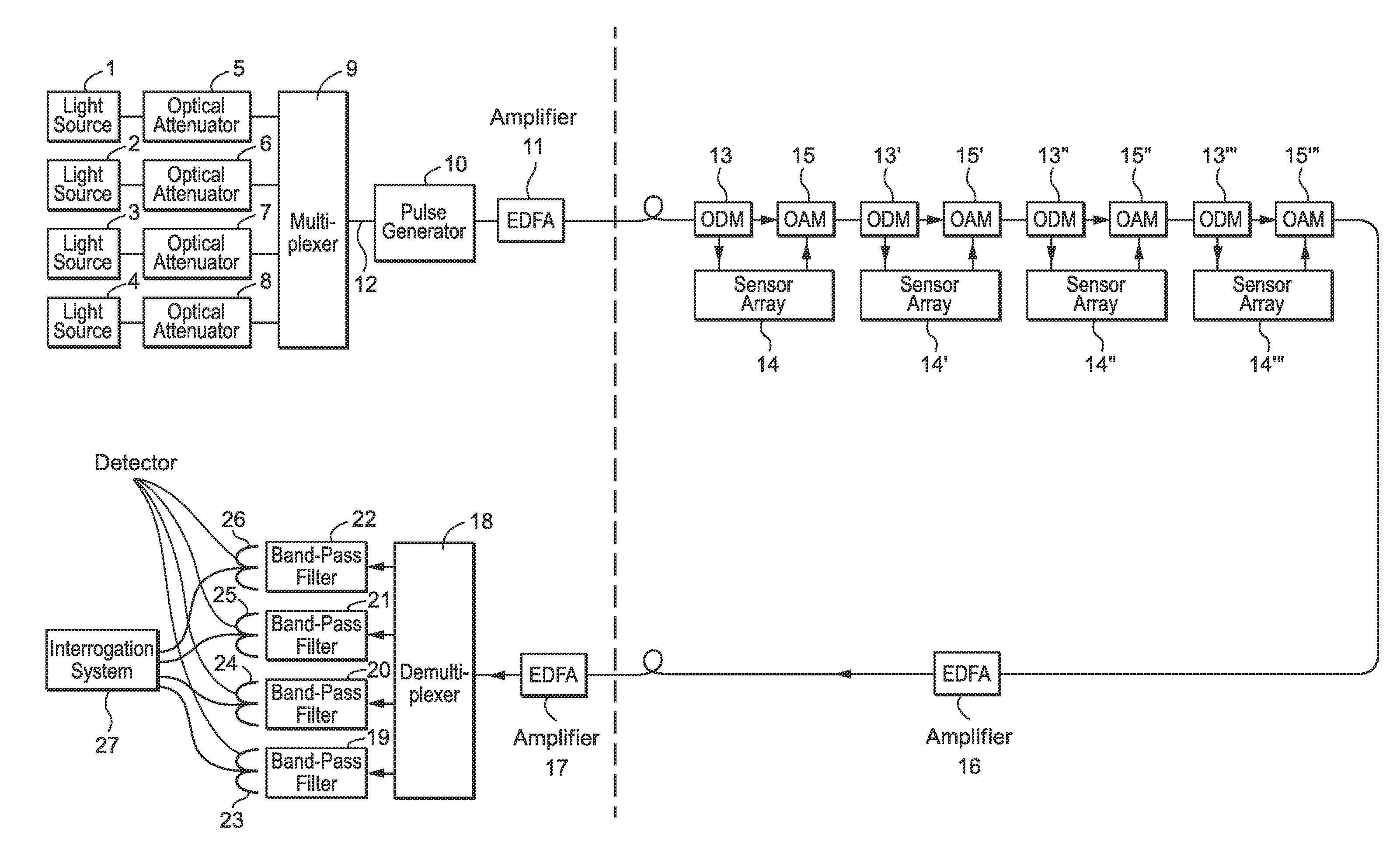
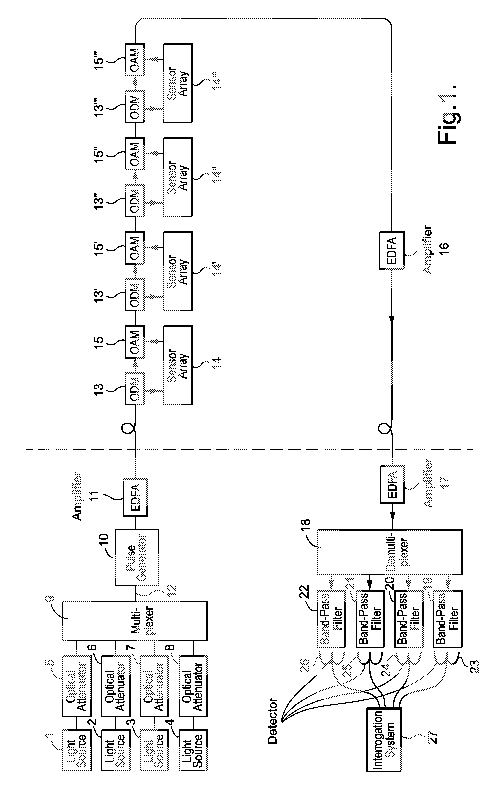
[0037]FIGS. 1, 4 and 5 illustrate examples of the present invention for sensor assemblies used to monitor hydrophones. Optical fibres connect the various components of the assemblies together. In this application the term ‘dry end’ indicates the components that are on-board a ship, whereas the term ‘wet end’ indicates the components that are in the water.

[0038]FIG. 1 shows a schematic representation of a simple optical fibre sensor assembly in accordance with the present invention, comprising a source of a plurality of different substantially monochromatic signals (in this case four, denoted λ1, λ2, λ3, λ4), the source comprising four individual monochromatic light sources 1, 2, 3, 4 (each being distributed feedback erbium doped fibre laser sources). There are also four optical attenuators 5, 6, 7, 8; a wavelength multiplexer 9; a pulse generator 10; and a first erbium-doped fibre amplifier (EDFA) 11. These are all in the dry end. In the wet end are four optical drop multiplexers (O...


PUM


Abstract

An optical fiber sensor assembly comprises a source of a plurality of different frequency substantially monochromatic signals (1, 2, 3, 4); a modulator connected to the output of the source to produce a train of output pulses of the monochromatic signals; a plurality of sensor sub-assemblies connected to the output of the modulator, each sub-assembly comprising an optical drop multiplexer (ODM) (13), a sensor array (14) comprising a plurality of sensor elements and an optical add multiplexer (OAM) (15); a wavelength demultiplexer (WDM), having an input coupled to the sub-assemblies output; a plurality of detectors, each detector having an input connected to receive a respective output of the WDM and providing at an output thereof a signal corresponding to a respective frequency of the modulated monochromatic signals; and an interrogation system, having a plurality of inputs connected such that each input receives the output signal from a respective detector.

Description

[0001]This applicatinon is the U.S. national phase of international application PCT / GB00 / 01300, filed in English on 6 Apr. 2000, which designated the U.S. PCT / GB00 / 01300 claims priority to GB Application No. 9908075.6 filed 9 Apr. 1999. The entire contents of these applications are incorporated herein by reference.BACKGROUND OF THE INVENTION[0002]1. Field of the Invention[0003]This invention relates to an optical fibre sensor assembly. More particularly, this invention relates to optical fibre sensor assemblies used to sense changes in temperature, strain, pressure, magnetic fields, electric fields, displacement and acceleration.[0004]2. Discussion of the Prior Art[0005]Many such assemblies, comprising arrays of sensor elements, have been made. They are optically addressed using a variety of well-known multiplexing techniques and combinations thereof, see for example U.S. Pat. No. 5,365,359. In such assemblies, the number of sensors that can be multiplexed is limited for a variety o...

Claims


Application Information

Patent Timeline
IPC IPC(8): G02B6/00G01L1/24G01B11/16G01D5/353G01D21/00G01K11/12G01L9/00G01P15/03G01R15/22G01V1/18G01V8/16G08C15/00G08C15/02G08C23/04
CPCG01D5/35383
Inventor CRANCH, GEOFFREY A
Owner OPTASENSE HLDG LTD
Learn More