
High fidelity time domain for spacecraft emulation systems

a time domain and spacecraft technology, applied in memory systems, compasses, program control, etc., can solve the problems of high cost and/or inadequate system-level ground testing to verify the full system performance of spacecraft and associated ground systems, system under test may yield inaccurate results or become inoperable, and require a substantial amount of effort. , to achieve the effect of high fidelity

Inactive Publication Date: 2013-02-05
THE BOEING CO
View PDF7 Cites 15 Cited by
  • Summary
  • Abstract
  • Description
  • Claims
  • Application Information

AI Technical Summary

Benefits of technology

The present invention provides a low-cost and high fidelity system for testing spacecraft and a ground system. It also allows for automatic modification of embedded processor clocks to duplicate the precise behavior of operational systems and investigate operational envelopes. Additionally, it synchronizes simulation engines and allows for more precise timestamping of data transmitted to external systems. Overall, embodiments of this invention improve the accuracy and reliability of testing and simulation for space vehicles and associated systems.

Problems solved by technology

However, system-level ground testing to verify full system performance of a spacecraft and associated ground system can be costly and / or inadequate.
Otherwise, the system under test may yield inaccurate results or become inoperative.
Known implementations of such systems require a substantial amount of effort to achieve some measure of time domain fidelity and must extrapolate test results to achieve some level of verification and validation.
The resulting simulation was a function of the operator's hand-eye coordination and subject to propagation delays and uncertainties within the operating system.
Some of these tuning mechanisms were automated and complex.
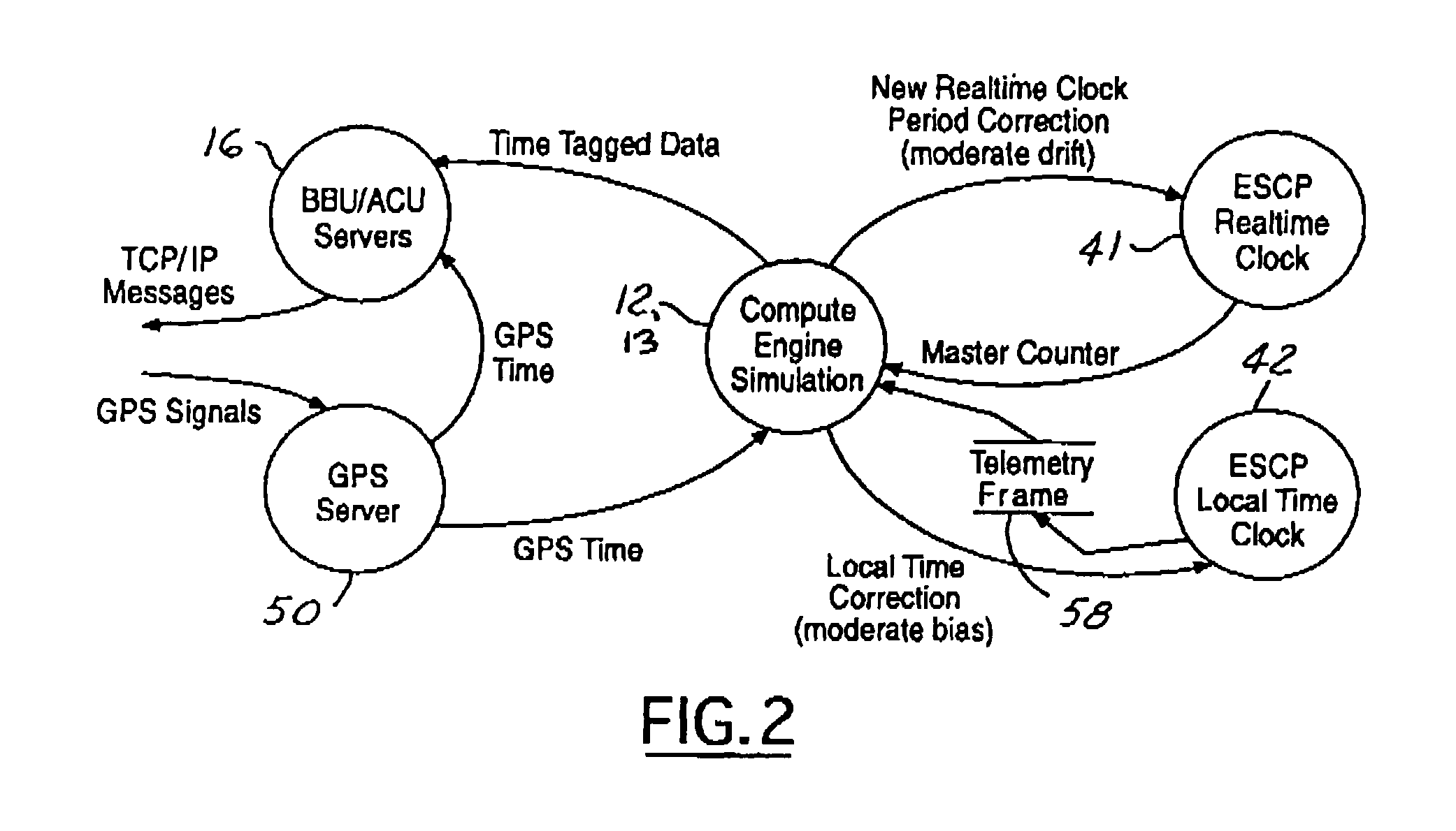
Accurate time keeping is desirable to simulate real world situations and the U.S. Pat. No. 5,808,921 has limited functionality because the several oscillators used to create clocks are subject to drift rates and biases that result is system clocks that have marginal accuracy and lack any definitive level of synchronization.
Consequently the time domain fidelity of the test environment is marginally sufficient and diminishes over time.
As a result, the fidelity of the test environment and the validity of the results are questionable.
When involved in long-term test, the degradation often causes premature termination of the testing.

Method used


Image

  • High fidelity time domain for spacecraft emulation systems
  • High fidelity time domain for spacecraft emulation systems
  • High fidelity time domain for spacecraft emulation systems

Examples


Embodiment Construction

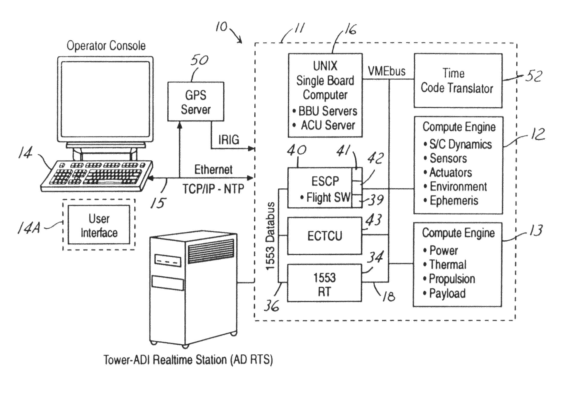
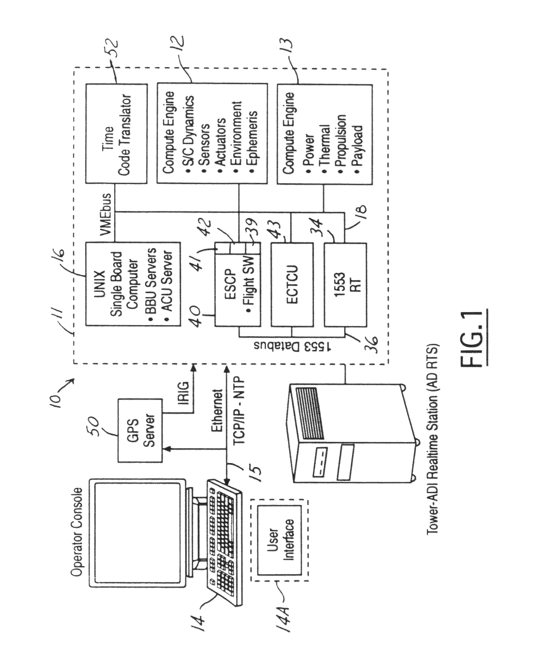
[0019]FIG. 1 is a block diagram of a real-time spacecraft simulation system 10 in accordance with the present invention. The real-time spacecraft simulation system 10 can be embodied by an Applied Dynamics Real Time Station (AD RTS) 11 manufactured by Applied Dynamics. The AD RTS 11 system is a stand-alone VMEbus-based real-time simulation and analysis system which uses a mixture of 9 U×400 mm ADI or commercial off the shelf (COTS) processor and input / output cards. Physically, the AD RTS system can be contained in a mini-tower housing.

[0020]The real-time spacecraft simulation system 10 includes one or more simulation engines (SE) 12, 13 which are used to simulate system dynamics in real time. For an AD RTS system 11, the simulation engines 12, 13 are in the form of processor cards installed therein. Simulation engines 12,13 may both have a real time clock with a real time clock period.

[0021]Each simulation engine 12, 13 are a single board computer (SBC) that solves the dynamic equat...


PUM


Abstract

An emulation system includes a central time source generating a time reference and an emulated spacecraft control processor which contains an embedded processor that provides an emulated input / output interface to communicate simulated spacecraft data. The embedded processor processes the simulated spacecraft data and contains a real time clock engine having a real-time clock period. The system further has a first simulation that processes attitude control system data from the emulated spacecraft control processor to simulate an attitude control system of the spacecraft in real-time. The first simulation engine operative to produce sensor data for input to the emulated spacecraft control processor based on the simulated system dynamics and adjusts the real time clock period in response to the time reference.

Description

TECHNICAL FIELD[0001]The present invention relates generally to spacecraft simulation, and more particularly to a complete spacecraft simulation system that accommodates high fidelity time domain test applications.BACKGROUND ART[0002]The increasing size and complexity of various spacecraft and associated subsystems therefore have created a need for detailed validation and verification before deployment. Examples of spacecraft subsystems requiring validation and verification include: (i) multiprocessor-based systems which can have complex software architectures; (ii) fault detection, isolation and response systems providing extended autonomous operations; (iii) multiple-articulated payloads and multibody control; (iv) precision payload pointing systems with multiple interacting elements; and (v) sophisticated ground software for automated spacecraft operations.[0003]However, system-level ground testing to verify full system performance of a spacecraft and associated ground system can...

Claims


Application Information

Patent Timeline
IPC IPC(8): G06G7/48G06F1/12G01G7/00G06F9/455G01K19/00G01L27/00G01C25/00G01C17/38
CPCB64G7/00
Inventor GOLD, JEFFREY J.HASKELL, JOHN D.KOZA, DAVID L.SURACE, MICHAEL J.ZAMMIT, STEVEN R.
Owner THE BOEING CO
Learn More