V-belt type continuously variable transmission

a technology of continuously variable transmission and belt, which is applied in the direction of gears, cycle equipments, guards, etc., can solve the problems of increasing the size and complexity of the v-belt type continuously variable transmission, and the limited clutch capacity, so as to prevent the transmission of engine vibration and prevent the generation of noise

Inactive Publication Date: 2013-02-26
KAWASAKI HEAVY IND LTD
View PDF12 Cites 32 Cited by
  • Summary
  • Abstract
  • Description
  • Claims
  • Application Information

AI Technical Summary

Benefits of technology

[0010]The present invention addresses the above described condition, and an object of the present invention is to support a drive shaft on both sides with high support rigidity in a V-belt type continuously variable transmission attached to a crankshaft via a centrifugal clutch without increasing the number of parts.
[0012]According to the above configuration, it is possible to support the drive shaft on the both sides without providing a separate shaft support member from the transmission case assembly for supporting the drive shaft of the V-belt type continuously variable transmission. Thus, it is possible to easily perform assembly work of the transmission case assembly and also reduce the number of parts of the V-belt type continuously variable transmission.
[0015]According to the above configuration, the other end of the drive shaft is supported by the boss portion formed in the transmission cover made of aluminum or an aluminum alloy. Thus, it is possible to enhance the support rigidity of the drive shaft and also improve the strength of the transmission cover. In addition, thermal radiation is also improved.
[0017]According to the above configuration, it is also possible to simplify a support structure for the one end of the drive shaft.
[0019]According to the above configuration, it is possible to enhance the rigidity of the transmission cover without increasing the thickness of the transmission cover so as to improve support strength of the other end of the drive shaft. Particularly, when the reinforced-rib is formed radially from the boss portion, it is possible to concentrically enhance the rigidity of the boss portion and the vicinity thereof. It is also possible to reduce vibration of the transmission cover by the reinforced-rib so as to decrease the generation of noise.
[0021]According to the above configuration, with a dust prevention effect as a matter of course, it is possible to prevent transmittance of the vibration of the engine and the like to the transmission cover so as to prevent the generation of the noise.

Problems solved by technology

Thus, the V-belt type continuously variable transmission is increased in size and complicated.
Further, only with friction force between the V-belt and the movable sheave, capacity of the clutch is limited.

Method used


Image

  • V-belt type continuously variable transmission
  • V-belt type continuously variable transmission
  • V-belt type continuously variable transmission

Examples


Embodiment Construction

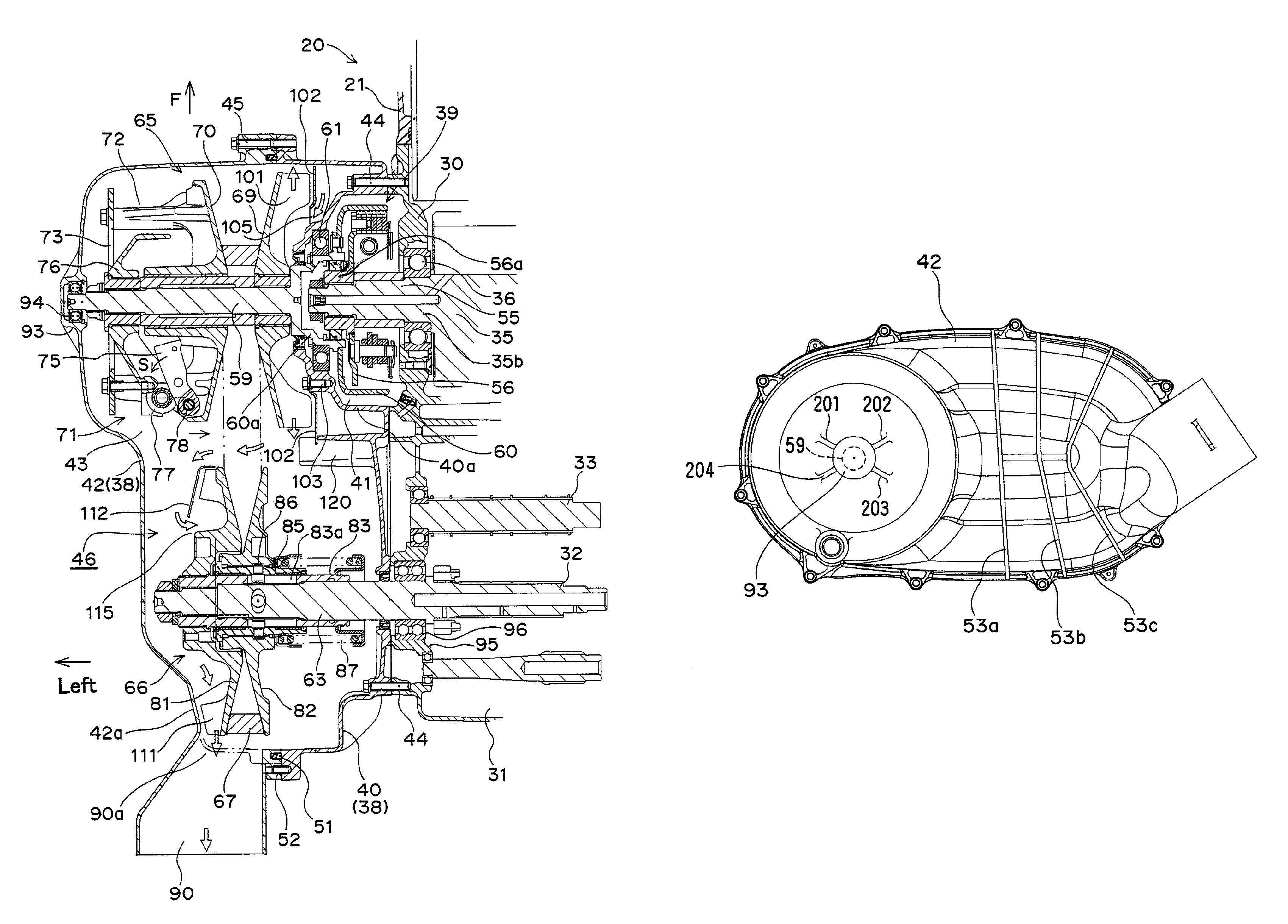
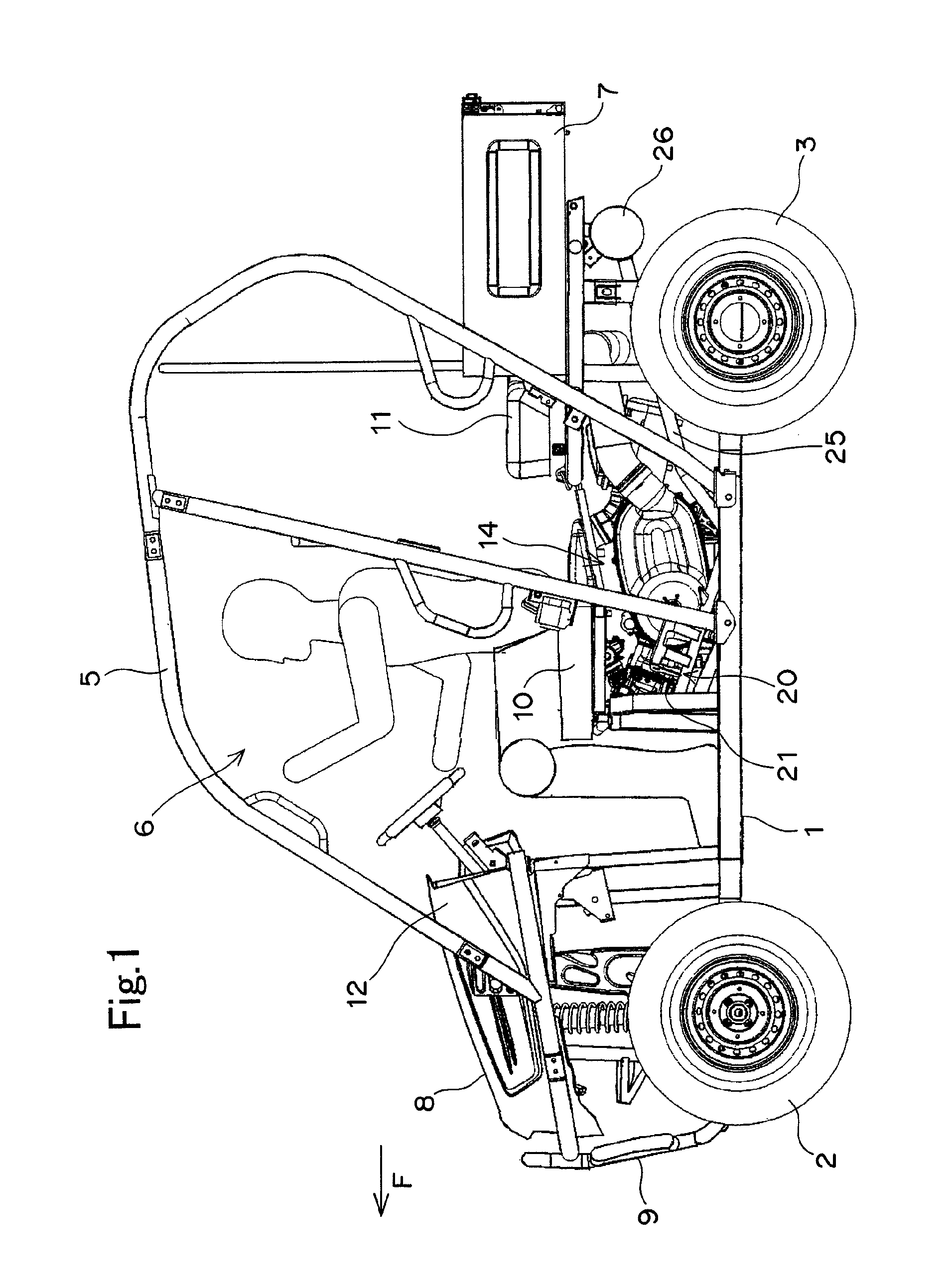
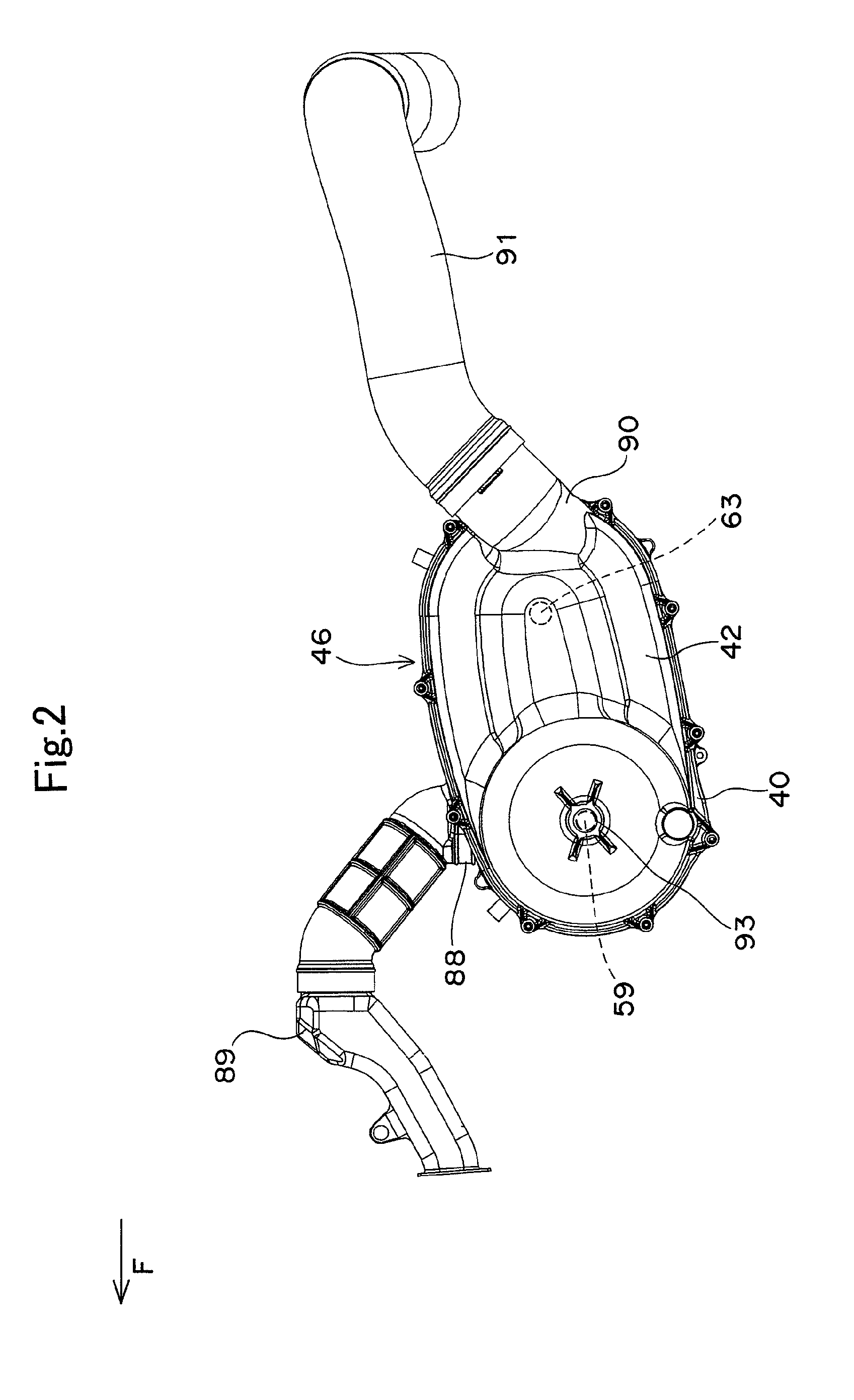
[0029]FIGS. 1 to 4 show an engine provided with a V-belt type continuously variable transmission according to a first embodiment of the present invention and a four-wheeled vehicle. One embodiment of the present invention will be described based on the figures.

[0030]FIG. 1 is a left side view of the four-wheeled vehicle. A small-sized four-wheeled vehicle for irregular terrain (a so-called utility vehicle) is provided with a pair of left and right front wheels 2 in a front part of a vehicle frame 1, a pair of left and right rear wheels 3 in a rear part of the vehicle frame 1, a cabin 6 surrounded by a cabin frame 5 between the front wheels 2 and the rear wheels 3, a loading platform 7 on the rear side of the cabin 6, fenders (not shown) respectively on the upper side of the front wheels 2 and on the upper side of the rear wheels 3, and a bonnet 8, a bumper 9 and the like on the front side of the cabin 6.

[0031]A front seat 10 formed in a bench shape is installed in a front half part ...


PUM


Abstract

A V-belt type continuously variable transmission includes a drive pulley assembly provided on a drive shaft, a driven pulley assembly provided on a driven shaft, a V-belt looped over both the pulley assemblies, and a transmission case assembly housing both the pulley assemblies and the V-belt. One end of the drive shaft in the shaft direction is coupled to an output side rotation member of a centrifugal clutch, and the other end of the drive shaft is rotatably supported on a boss portion formed in the transmission case assembly.

Description

BACKGROUND OF THE INVENTION[0001]1. Field of the Invention[0002]The present invention relates to a V-belt type continuously variable transmission and, particularly to a V-belt type continuously variable transmission attached to a crankshaft of an engine via a centrifugal clutch.[0003]2. Description of the Related Art[0004]As V-belt type continuously variable transmissions, Japanese Patent Laid Open Application No. 2003-184972 discloses a type having a clutch function capable of cutting mechanical power transmission between a V-belt and drive pulley assembly, and Japanese Patent Laid Open Application No. 2007-71255 discloses a type in which a V-belt and a drive pulley assembly are connected so that mechanical power can be transmitted therebetween and a centrifugal clutch or the like is separately arranged between a drive shaft and a crankshaft of an engine.[0005]In the former type, since there is no need for separately providing the centrifugal clutch or the like, it is possible to s...

Claims


Application Information

Patent Timeline
Patent Type & Authority Patents(United States)
IPC IPC(8): F16H59/00F16H9/12
CPCF16H9/18F16H57/03F16H57/035F16H55/563F16H57/032F16H57/0415F16H57/0489F16H63/067F16H2057/0203
Inventor MORITA, TAISUKE
Owner KAWASAKI HEAVY IND LTD
Why Eureka
Try Eureka