High efficiency bridgeless PFC converter and method

a converter and high-efficiency technology, applied in the direction of electric variable regulation, process and machine control, instruments, etc., can solve the problems of reducing the efficiency of the ac-dc power stage, and achieve the effects of improving efficiency, reliability and cost, and reducing power loss

Active Publication Date: 2013-02-26
HUAWEI DIGITAL POWER TECH CO LTD
View PDF10 Cites 25 Cited by
  • Summary
  • Abstract
  • Description
  • Claims
  • Application Information

AI Technical Summary

Benefits of technology

[0009]An advantage of an embodiment of the present invention is reducing the power loss as well as common mode noise of a bridgeless factor correction circuit so as to improve the efficiency, reliability and cost of a power system having the bridgeless factor correction circuit.

Problems solved by technology

The considerable power losses from the full bridge rectifier may further reduce the efficiency of the ac-dc power stage.

Method used


Image

  • High efficiency bridgeless PFC converter and method
  • High efficiency bridgeless PFC converter and method
  • High efficiency bridgeless PFC converter and method

Examples


Embodiment Construction

[0021]The making and using of the presently preferred embodiments are discussed in detail below. It should be appreciated, however, that the present invention provides many applicable inventive concepts that can be embodied in a wide variety of specific contexts. The specific embodiments discussed are merely illustrative of specific ways to make and use the invention, and do not limit the scope of the invention.

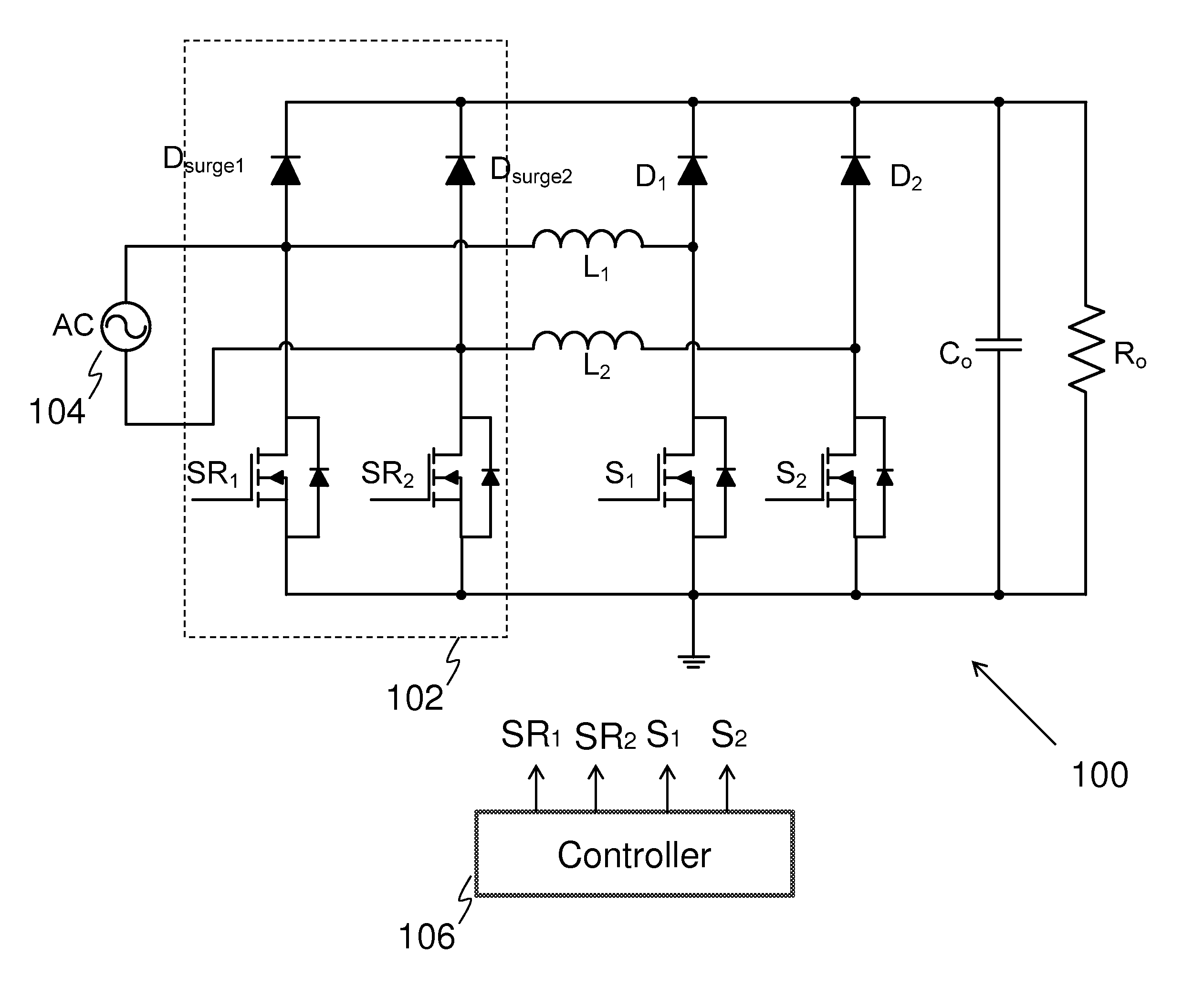
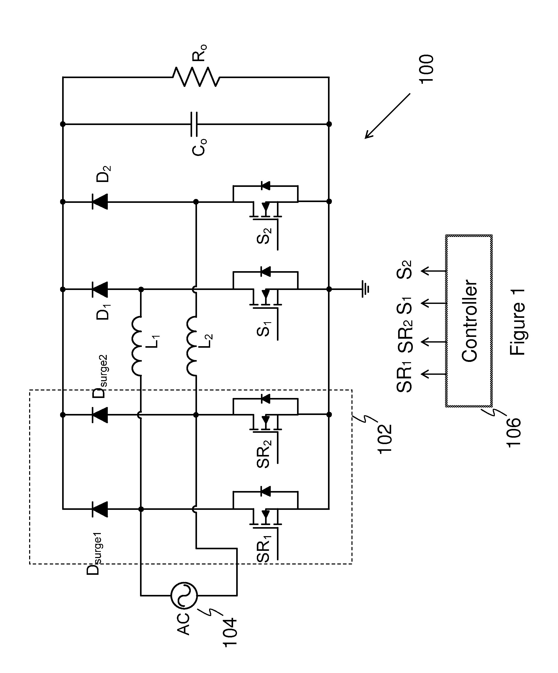
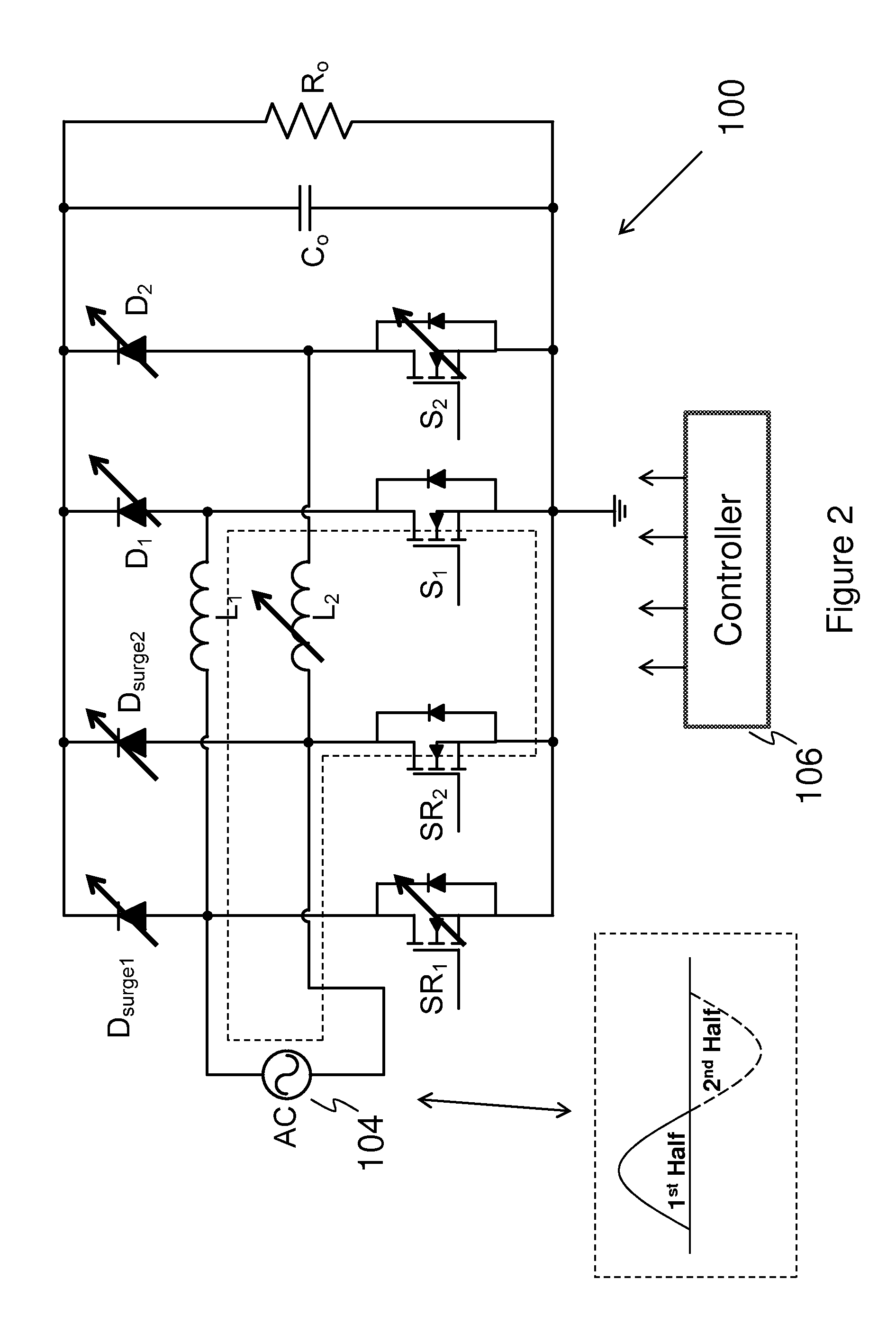
[0022]The present invention will be described with respect to preferred embodiments in a specific context, namely a high efficiency bridgeless power factor correction circuit. The invention may also be applied, however, to a variety of power factor correction circuits operating in different modes (e.g., discontinuous conduction mode, critical conduction mode or continuous conduction mode), employing different modulation mechanisms (e.g., leading edge pulse width modulation, trailing edge pulse width modulation or pulse frequency modulation) and adopting different control sche...


PUM


Abstract

An embodiment bridgeless power factor correction circuit comprises a first boost converter and a second boost converter connected in parallel. A first switch is coupled between the input of the first boost converter and ground. A second switch is coupled between the input of the second boost converter and ground. Both the first switch and the second switch help to reduce the common mode noise of the bridgeless power factor correction circuit. The bridgeless power factor correction circuit further comprises two surge protection diodes coupled between the inputs of two boost converters and the output of the bridgeless power factor correction circuit.

Description

TECHNICAL FIELD[0001]The present invention relates to devices and methods for bridgeless power factor correction converters, and more particularly, to devices and methods for bridgeless power factor correction converters with high efficiency.BACKGROUND[0002]A telecommunication network power system usually includes an ac-dc stage converting the power from the ac utility line to a 48V dc distribution bus. A conventional ac-dc stage may comprise a variety of EMI filters, a bridge rectifier formed by four diodes, a power factor correction circuit and an isolated dc / dc power converter. The bridge rectifier converts an ac voltage into a full-wave rectified dc voltage. Such a full-wave rectified dc voltage provides a dc input voltage for the power factor correction circuit. The power factor correction circuit may be implemented by employing a power converter including a boost converter. By employing an appropriate control circuit, the boost converter is capable of shaping the input line cu...

Claims


Application Information

Patent Timeline
Patent Type & Authority Patents(United States)
IPC IPC(8): H02H7/00H02H9/00H02H9/04H02H3/22H02H3/20
CPCH02M1/4225H02H7/1216H02H9/042H02H3/20H02H3/22Y02B70/126Y02B70/10H02M1/0085
Inventor MAO, HENGCHUNFU, DIANBOCAI, BING
Owner HUAWEI DIGITAL POWER TECH CO LTD
Why Eureka
Try Eureka