
Protective film removing device, mixed chemical solution recovering method and program storage medium

a technology of protective film and recovery method, which is applied in the direction of photomechanical equipment, cleaning using liquids, instruments, etc., can solve the problems of high recovery percentage of chemicals, high cost of protective film and former protective film, and high cost of protective film and other problems, to achieve the effect of reducing the work of separating the mixed chemical solution, high recovery percentage and recycling of expensive removers

Inactive Publication Date: 2013-03-05
TOKYO ELECTRON LTD
View PDF8 Cites 4 Cited by
  • Summary
  • Abstract
  • Description
  • Claims
  • Application Information

AI Technical Summary

Benefits of technology

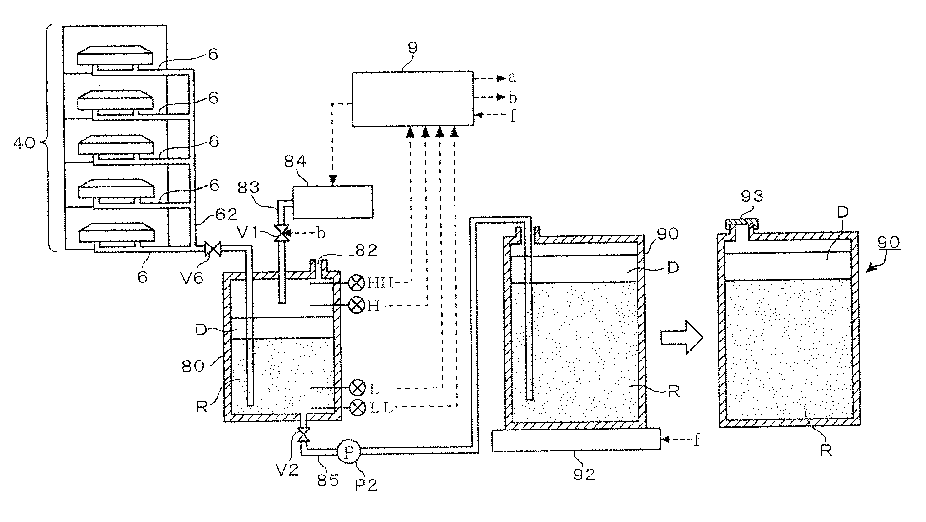
The present invention is related to a method of recovering a mixed chemical solution containing a remover for removing a water-repellent protective film formed on a surface of a substrate, and the remover and the protective film dissolved in the remover. The invention aimed to provide a method that can recover the mixed chemical solution with a high recovery percentage and recycle the expensive remover. The method includes using a volatilization preventing liquid to prevent the mixed chemical solution from evaporating during storage and transfer to the recovery tank. By temporarily storing the mixed chemical solution in the intermediate tank and using the volatilization preventing liquid, the method reduces work for separating the mixed chemical solution from water and limits the volatilization of the mixed chemical solution to the least possible extent.

Problems solved by technology

However, the latter protective film is more costly than the former protective film.
The protective film of a fluorocarbon resin and the fluorocarbon solvent are costly.
Since those chemicals are highly volatile, the recovery percentage of those chemicals is very small.

Method used


Image

  • Protective film removing device, mixed chemical solution recovering method and program storage medium
  • Protective film removing device, mixed chemical solution recovering method and program storage medium
  • Protective film removing device, mixed chemical solution recovering method and program storage medium

Examples


Embodiment Construction

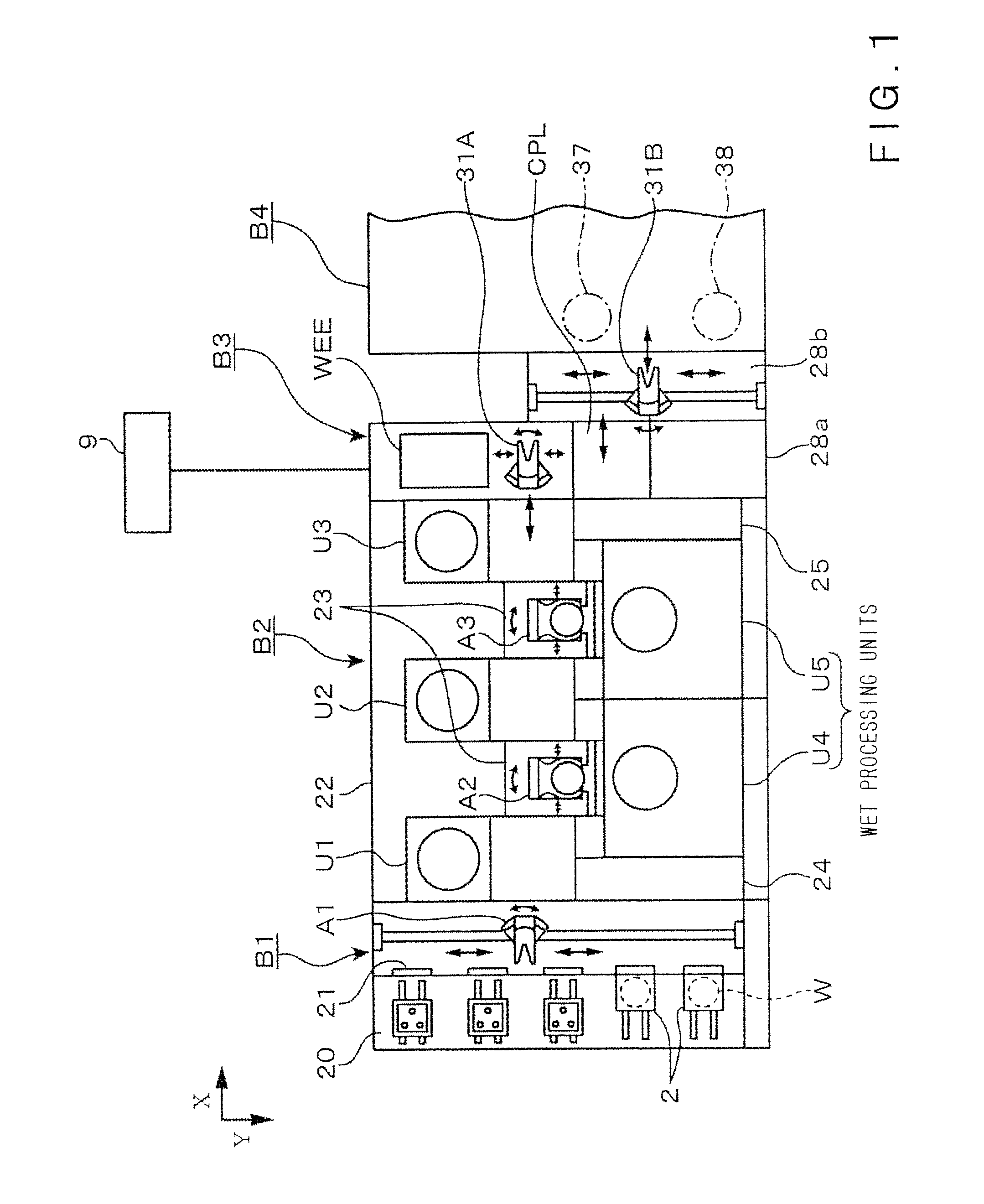
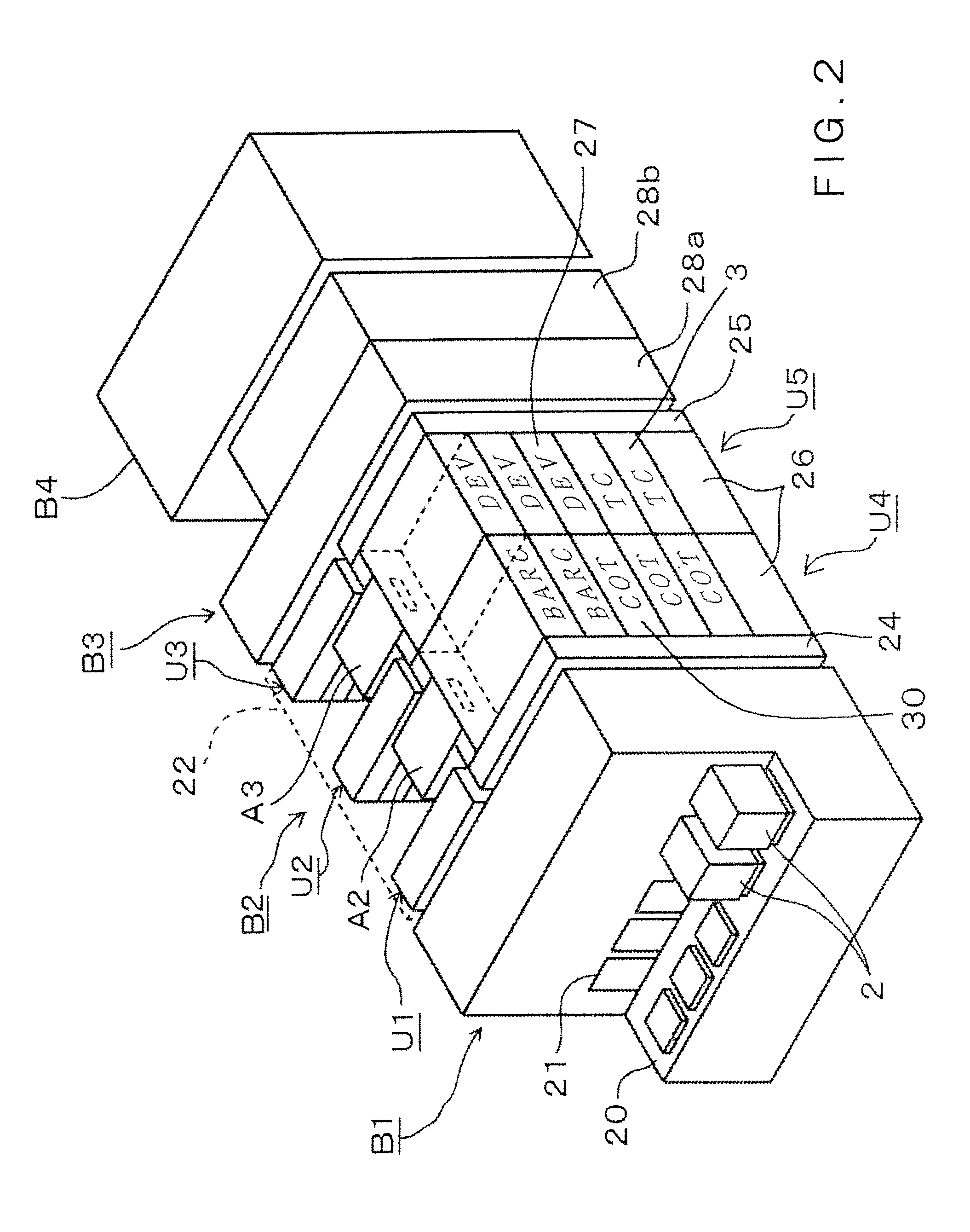
[0051]A coating and developing system including a protective film removing device in a preferred embodiment according to the present invention and combined with an exposure system will be briefly described prior to the description of the protective film removing device with reference to FIGS. 1 to 3. Referring to FIGS. 1 and 2, a carrier 2 containing, for example, thirteen wafers W, namely, substrates, in an airtight fashion is delivered to a carrier station B1. The carrier station B1 is provided with a stage 20 capable of supporting a plurality of carriers 2 thereon, a wall disposed behind the stage 20 and provided with closable openings 21, and a transfer device A1 for taking out the wafers W from the carrier 2 through the closable opening 21.

[0052]A processing block B2 surrounded by a box 22 is disposed behind and joined to the carrier station B1. The processing block B2 includes shelf units U1, U2 and U3 arranged backward in that order, wet processing units U4 and U5, main carry...


PUM

PropertyMeasurementUnit
wavelengthaaaaaaaaaa
specific gravityaaaaaaaaaa

Abstract

The present invention improves recover percentage at which a mixed chemical solution discharged from a protective film removing device.The protective film removing device includes: a recovery line communicating with an atmosphere surrounding a substrate to recover a mixed chemical solution, an intermediate tank connected to the outlet end of the recovery line, a volatilization preventing liquid supply means for supplying a volatilization preventing liquid having a specific gravity smaller than that of the mixed chemical solution into the intermediate tank in advance, a transfer line having an inlet end connected to the intermediate tank and provided with a valve, a recovery tank connected to an outlet end of the transfer line, a liquid quantity monitoring means for monitoring a quantity of a liquid contained in the intermediate tank, and a control means for opening the valve of the transfer line to transfer the liquid contained in the intermediate tank to the recovery tank when it is decided that the quantity of the liquid contained in the intermediate tank reached a predetermined quantity on the basis of a signal provided by the liquid quantity monitoring means.

Description

BACKGROUND OF THE INVENTION[0001]1. Field of the Invention[0002]The present invention relates to a protective film removing device for removing a water-repellent protective film formed on a surface of a substrate by dissolving the water-repellent protective film in a liquid remover and recovering a mixed chemical solution, which is a mixture of the liquid remover and a solution produced by dissolving the water-repellent protective film in the liquid remover, and a method of recovering the mixed chemical solution.[0003]2. Description of the Related Art[0004]A photolithographic technique for a semiconductor device fabricating process includes, for example, the steps of forming a resist film on a semiconductor wafer (hereinafter, referred to simply as “wafer”) exposing the resist film to light through a photomask, and developing the exposed resist film by a developing process to form a desired resist pattern.[0005]An exposure technique disclosed in JP-A 2005-175079 forms a liquid layer...

Claims


Application Information

Patent Timeline
Patent Type & Authority Patents(United States)
IPC IPC(8): B08B3/04
CPCH01L21/6708H01L21/6715B05C11/10G03F7/70533
Inventor YAMAMOTO, TAROYOSHIHARA, KOUSUKE
Owner TOKYO ELECTRON LTD
Learn More