
Solder paste

a technology of solder paste and slurry, which is applied in the field of solvent paste, can solve the problems of inability to use paste at all, and poor wettability of powder, so as to facilitate the molten low melting point metal, the length of contact between the alloy and the lands of printed circuit boards or the terminals of electronic parts is increased, and the effect of improving the wettability

Active Publication Date: 2013-03-05
SENJU METAL IND CO LTD
View PDF12 Cites 9 Cited by
  • Summary
  • Abstract
  • Description
  • Claims
  • Application Information

AI Technical Summary

Benefits of technology

The Ni-plated solder paste achieves strong solder bonding with self-alignment effects, correcting positional deviations and maintaining bonding strength even at high temperatures, overcoming the limitations of existing high-temperature solders.

Problems solved by technology

The use of Pb is being regulated on a global scale, but a practicable high-temperature solder which does not contain Pb has not been developed.
However, if these solder alloys are formed into solder powder for use in a solder paste, due to the susceptibility to oxidation of Zn and Al which are the main components of the powder, a thick oxide film is formed on the surface of the powder, thereby causing the powder to have an extremely poor wettability.
When such powder is mixed with a flux to form a solder paste, the resulting paste is not at all capable of actual use, since non-wetting occurs when it is used for soldering of electronic parts.
However, if this high-temperature solder is used at a temperature of not higher than approximately 300° C., which is the guaranteed heat resisting temperature of a chip part, since this temperature is high compared to 1083° C. which is the melting temperature of Cu balls, the solder itself has poor wettability, and reliable bonding cannot take place, thereby causing the formation of only weak joints.
Therefore, although a reaction between the Sn balls and the Cu balls to form an intermetallic compound occurs adequately, there is not enough time for molten Sn to wet the lands of a printed circuit board or the terminals of electronic part, resulting in insufficient spreading and inadequate joint strength.

Method used


Image

  • Solder paste
  • Solder paste
  • Solder paste

Examples


example 1

1. Low melting point alloy powder (particle diameter of powder: 2-15 μm)

[0038]1) Sn powder[0039]2) Sn-3.5 mass % Ag powder[0040]3) Sn-0.7 mass % Cu powder[0041]4) Sn-5 mass % Sb powder[0042]5) Sn-58 mass % Bi powder[0043]6) Sn-3.5 mass % Ag-0.5 mass % Cu powder[0044]7) Sn-58 mass % Bi-0.8 mass % Ag powder[0045]8) Sn-0.7 mass % Cu-0.3 mass % Sb powder[0046]9) Sn-5 mass % Sb-0.05 mass % Ni-0.1 mass % Co powder

2. High melting point powder (particle diameter of powder: 2-15 μm; the Ni content is a coating of the powder formed by electroless plating and having a composition of 95 mass % Ni-5 mass % P)[0047]1) Cu-0.2 mass % Ni powder[0048]2) Cu-1.0 mass % Ni powder[0049]3) Cu-1.5 mass % Ni powder[0050]4) Cu-2.0 mass % Ni powder[0051]5) Cu-7.0 mass % Ni powder[0052]6) Cu-3.0 mass % Sn powder[0053]7) Ag-0.5 mass % Ni powder[0054]8) Ag-3.0 mass % Ni powder[0055]9) Ag-7.0 mass % Ni powder[0056]10) Cu powder[0057]11) Ag powder

3. Mixed powder

[0058]The above-described low melting point alloy pow...

example 2

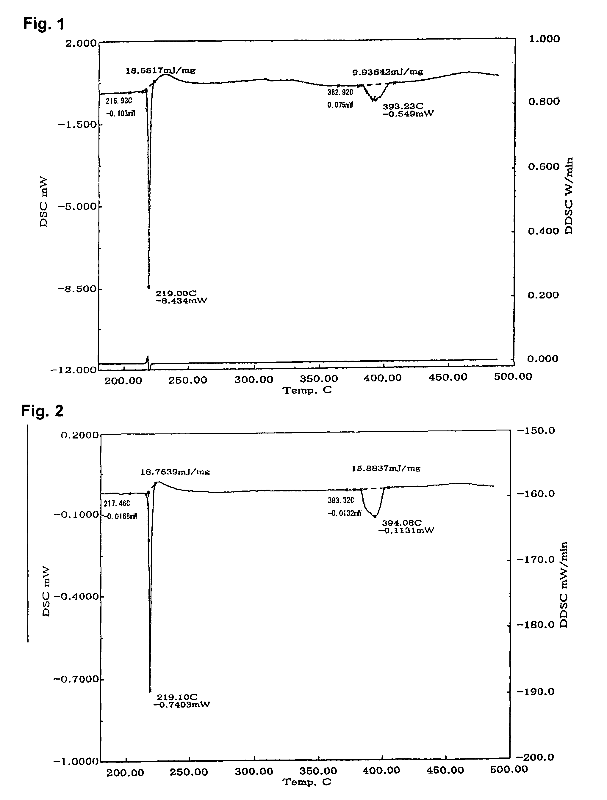
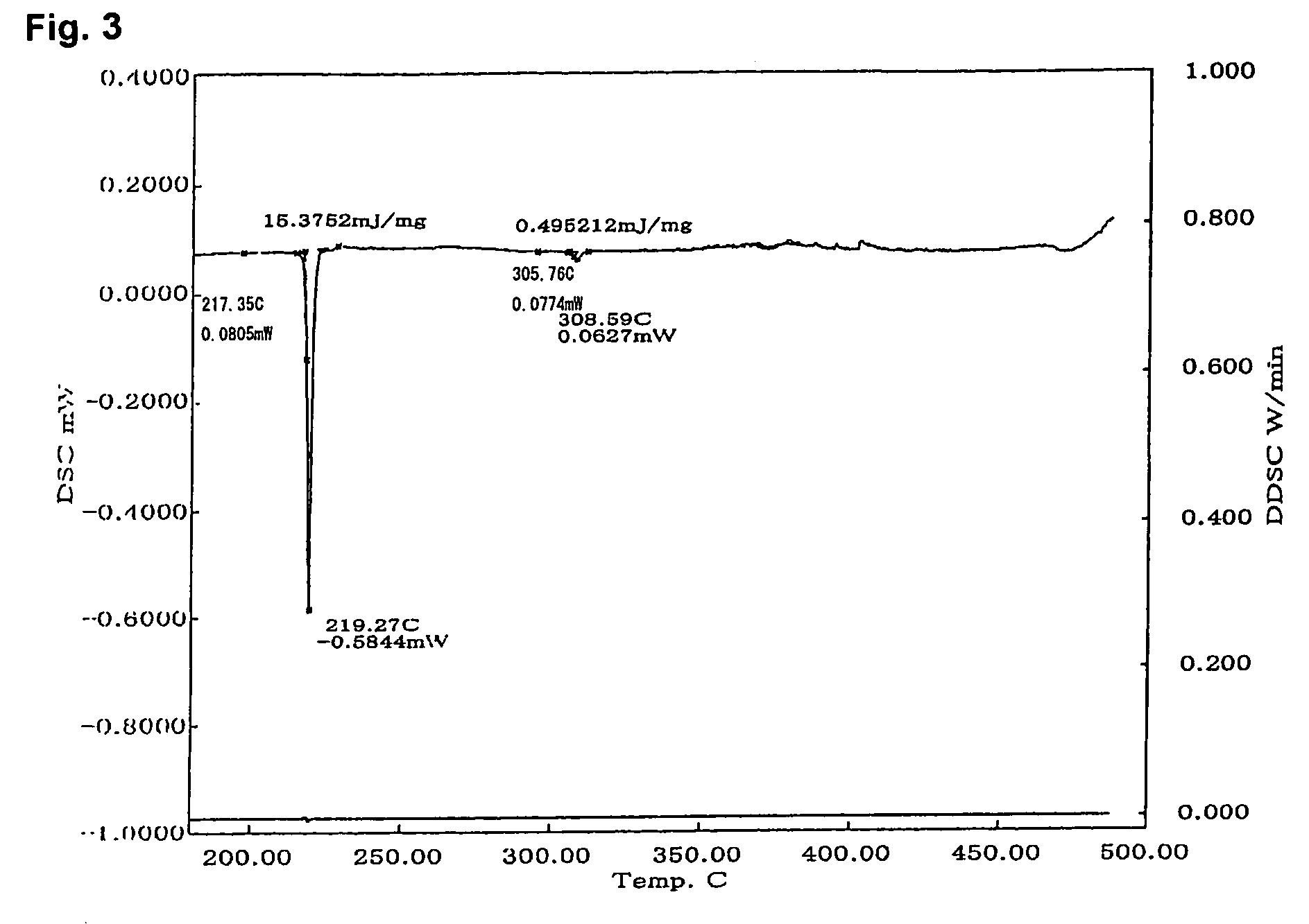
[0089]The amount of intermetallic compounds formed by each solder paste prepared in Example 1 was evaluated by measuring heat absorption using a DSC.

[0090]

TABLE 11st1st2ndsoliduspeaksolidus2nd1st heat2nd heatLow m.p.High m.p.temp.temp.temp.peakabsorptionabsorptionpowderpowder(° C.)(° C.)(° C.)temp.(mJ / mg)(mJ / mg)Inventive1SnCu—0.2Ni22723138640522.413.52SnCu—2.0Ni22723138540723.111.33Sn—3.5AgCu—0.2Ni21721938940220.614.14Sn—3.5AgCu—1.0Ni21721938741518.59.25Sn—3.5AgCu—1.5Ni21721940841923.7106Sn—3.5AgCu—2.0Ni21721940541622.110.27Sn—0.7CuCu—1.0Ni22723137940121.811.68Sn—3Ag—0.5CuCu—1.0Ni21721939540524.413.89Sn—3.5Ag—8InCu—1.0Ni19720839140819.613.610Sn—0.7Cu—0.3SbCu—1.0Ni22623038640222.812.411SnAg—0.5Ni22122235837722.912.912SnAg—3.0Ni22122335235823.113.1Comparative1SnCu23223338539522.614.22SnCu—7.0Ni23223330530818.20.43Sn—3.5AgCu21721939440820.613.74Sn—3.5AgCu—7.0Ni21721930530815.30.55SnAg221223————6SnAg—7.0Ni23123430430920.30.5

1. Test Method

[0091]1. Each of the solder pastes prepared in Ex...

example 3

[0100]The wettability of each solder paste prepared in Example 1 was evaluated from the molten state of a piece of solder at various temperatures with various heating times.

[0101]

TABLE 2Low m.p.High m.p.powderpowderWettabilityInventive1SnCu—0.2Ni2SnCu—2.0Ni3Sn—3.5AgCu—0.2Ni4Sn—3.5AgCu—1.0Ni5Sn—3.5AgCu—1.5Ni6Sn—3.5AgCu—2.0Ni7Sn—0.7CuCu—1.0Ni8Sn—3Ag—0.5CuCu—1.0Ni9Sn—3.5Ag—8InCu—1.0Ni10Sn—0.7Cu—0.3SbCu—1.0Ni11SnAg—0.5Ni12SnAg—3.0NiComparative1SnCu2SnCu—7.0Ni3Sn—3.5AgCu4Sn—3.5AgCu—7.0Ni5SnAg6SnAg—7.0Ni

1. Test Method

[0102]1. Each of the solder pastes prepared in Example 1 was printed with a squeegee on 50 mm×50 mm×0.8 mm alumina substrates through a metal mask having a thickness of 0.15 mm and having an opening measuring 30 mm×30 mm.

[0103]2. The alumina substrate was heated for 30 seconds or 120 seconds atop a solder bath set to 270° C. to obtain a solder piece bonded to the substrate.

2. Test Results

[0104]The resulting solder pieces are shown in Table 2.

[0105]In Comparatives 2, 4, and 6,...


PUM

PropertyMeasurementUnit
particle diameteraaaaaaaaaa
mass %aaaaaaaaaa
mass %aaaaaaaaaa

Abstract

High-temperature solders having a higher melting point than solder alloys used for soldering of printed circuit boards are used for internal bonding of electronic parts, but high-temperature solders which are free from Pb have not been developed. There exist high-temperature solders which comprises Sn balls and Cu balls and which perform bonding through the formation of an intermetallic compound without melting to form a single-phase structure, but they have poor wettability to the lands of a printed circuit board or electrodes of electronic parts and have not been used.A solder paste according to the present invention is provided by mixing flux with a powder mixture of Sn powder or an Sn based lead-free solder powder with Cu or Ag powder which has Ni plating formed on its surface. Although the solder paste performs bonding by means of an intermetallic compound without melting to form a single phase structure, the Ni plating acts as a barrier which retards the formation of the intermetallic compound so as to leave enough time to permit wetting of the lands of a printed circuit board or electrodes of an electronic part.

Description

TECHNICAL FIELD[0001]This invention relates to a solder paste which is formed by mixing a solder powder and a soldering flux and which can obtain a solder alloy for use in connection of electronic equipment. The solder alloy has excellent heat resistance and can exhibit high reliability in a high-temperature state.BACKGROUND ART[0002]In electronic equipment, electronic parts are disposed atop a circuit of printed circuit board or the like to perform prescribed functions. From long in the past, connection of electronic parts to printed circuit boards or other circuits has been performed using solder, which can perform connection at a low temperature, is inexpensive, and has high bonding reliability. Electronic parts used in electronic equipment need to have terminals such as part leads which are connected to printed circuit boards. Solder is also used inside electronic parts to connect terminals such as part leads to part components which perform the basic functions of the electronic...

Claims


Application Information

Patent Timeline
Patent Type & Authority Patents(United States)
IPC IPC(8): B32B15/01B32B15/02B23K1/00B32B15/20B22F1/10B22F1/17
CPCB22F1/0003B22F1/025B23K35/0244B23K35/26B23K35/262C22C5/00C22C9/02C22C9/06C22C13/00C22C13/02H05K3/3484B22F1/0059Y10T428/12028H05K2201/0215H05K2201/0218Y10T428/12181Y10T428/2982H05K3/3485B22F1/17B22F1/10B22F1/09B23K35/24
Inventor KATO, RIKIYAYAMAGATA, SAKIE
Owner SENJU METAL IND CO LTD
Learn More