Curing

a technology heat input, applied in the field of cure, can solve the problems of attractive methods, high heat input required to achieve rapid cure temperature, and lamp requires active cooling, etc., to enhance the reactivity of the system, enhance the spectral sensitivity of the photoinitiator in the ink to be extended, and optimise the reactivity of radiation curable ink.

Active Publication Date: 2013-03-19
AGFA NV
View PDF32 Cites 4 Cited by
  • Summary
  • Abstract
  • Description
  • Claims
  • Application Information

AI Technical Summary

Benefits of technology

[0016]By providing the inerting environment, for example a reduced oxygen environment, inhibition of cure of the fluid due to the oxygen in the environment can be reduced and thus the cure reaction can be accelerated by reducing the fluid's exposure to oxygen.
[0126]Other components of types known in the art may be present in the ink to improve the properties or performance. These components may be, for example, surfactants, defoamers, dispersants, stabilisers against deterioration by heat or light, reodorants, flow or slip aids, biocides and identifying tracers.

Problems solved by technology

However, the heat input required to achieve a temperature for rapid cure is often too high for this to be an attractive method.
One of the main problems in designing printers to print using curable ink is the provision of a suitable radiation source to effect the curing.
Firstly, little of the electrical energy consumed by the lamp is converted into UV energy. Typically only 10 to 15% of the input power effects emission in the desired wavelengths of 250 to 390 nm. The remainder is either emitted at other (mainly longer) wavelengths, or as heat. This heat must be taken away from the lamp by conduction or convection. This waste heat can cause problems because it can effect heating of the substrate to which the ink is being applied, and also because the lamp requires active cooling which is expensive, especially if the UV lamp is mounted on a moving carriage on the printing apparatus.
Secondly, the UV output obtained from the lamp is highly sensitive to the operating temperature of the lamp. It is difficult to control the operating temperature accurately, and hence to ensure that the emitted UV is constant. A more important problem is the speed of response of the lamp. Starting from cold, it can take half a minute or more to warm the lamp up to full operating temperature, during which time the UV output is rising to its rated value. This can be a particular problem for printers where the UV is needed intermittently during the scanning of the printhead assembly over the substrate. Keeping the UV lamp at full power all the time would be wasteful, and would also cause further problems associated with stray UV radiation from the lamp which could have safety implications and might lead to unwanted curing of the ink in the printheads themselves.
This keeps the bulb warm, but there is still a substantial amount of waste heat generated, which must be removed.
When considering the target material, for example a UV curing ink, it can be seen that it is very difficult to match the sensitivity of the ink to a set of very narrow emission lines which are spread over a range of frequencies.
Also, in many cases, the intensity of UV output along the length of a mercury discharge lamp is uneven.
This appears to be an unavoidable property of the lamps in practice, and can result in variations in the appearance of the final ink film.
Furthermore, the lamps (together with their reflectors, cooling and shuttering) are bulky and heavy.
This is particularly a disadvantage when the lamps are mounted on a moving carriage.

Method used


Image

  • Curing
  • Curing
  • Curing

Examples


example 1

UV Curable Ink for Use with a 382 Nm LED

[0194]Ink Formula A:

[0195]Propoxylated neopentylglycol diacrylate 74.91 parts

[0196]Solsperse 32000 (dispersant from Avecia) 0.48 parts

[0197]Irgalite Blue GLVO (blue pigment from Ciba) 1.44 parts

[0198]Genorad 16 (stabiliser from Rahn AG) 0.12 parts

[0199]Rapi-cure DVE-3 (difunctional vinyl ether from ISP Europe) 15.0 parts

[0200]Lucerin TPO (photoinitiator from BASF) 8.0 parts

[0201]Byk 307 (defoamer from BYK Chemie) 0.05 parts

[0202]The composition was an ink having a viscosity of 16 mPas at 25 C. The ink was coated onto self-adhesive vinyl and was successfully cured under reduced oxygen environment when exposed to an LED source which emitted radiation having a peak wavelength of 382 nm. The LEDs used were EIS09-OPOA9-02 of Roithner Lasertechnik.

example 2

UV Curable Ink for Use with a 405 Nm LED

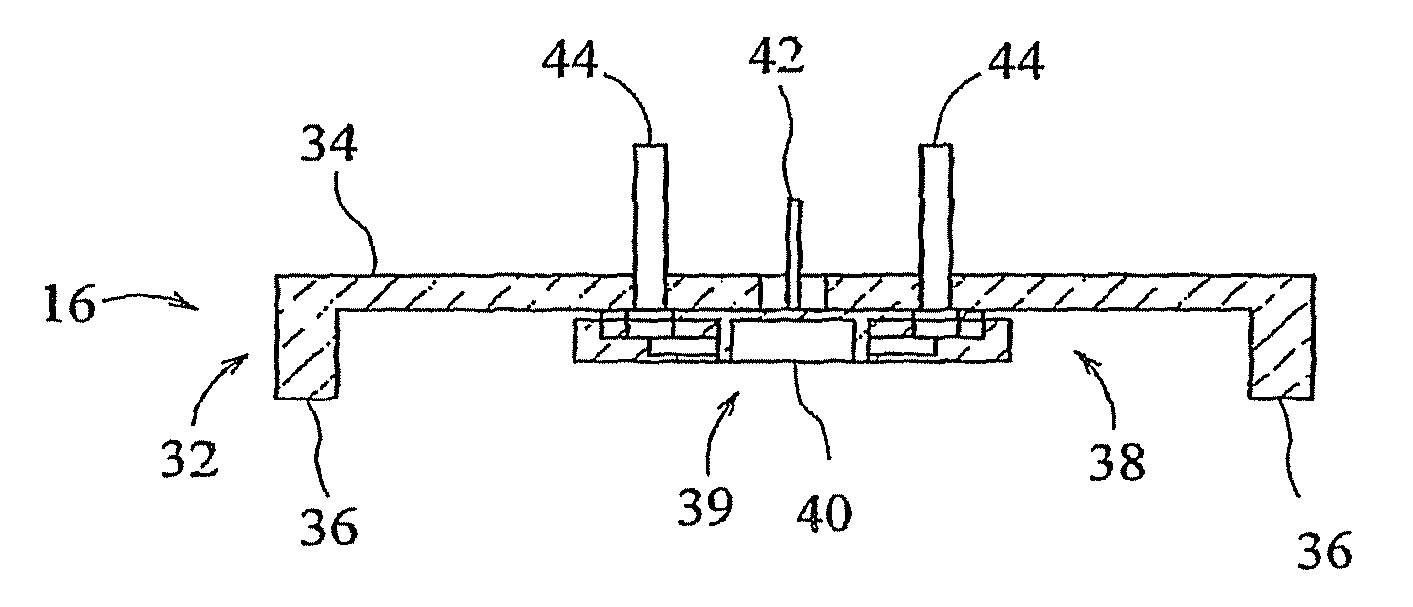
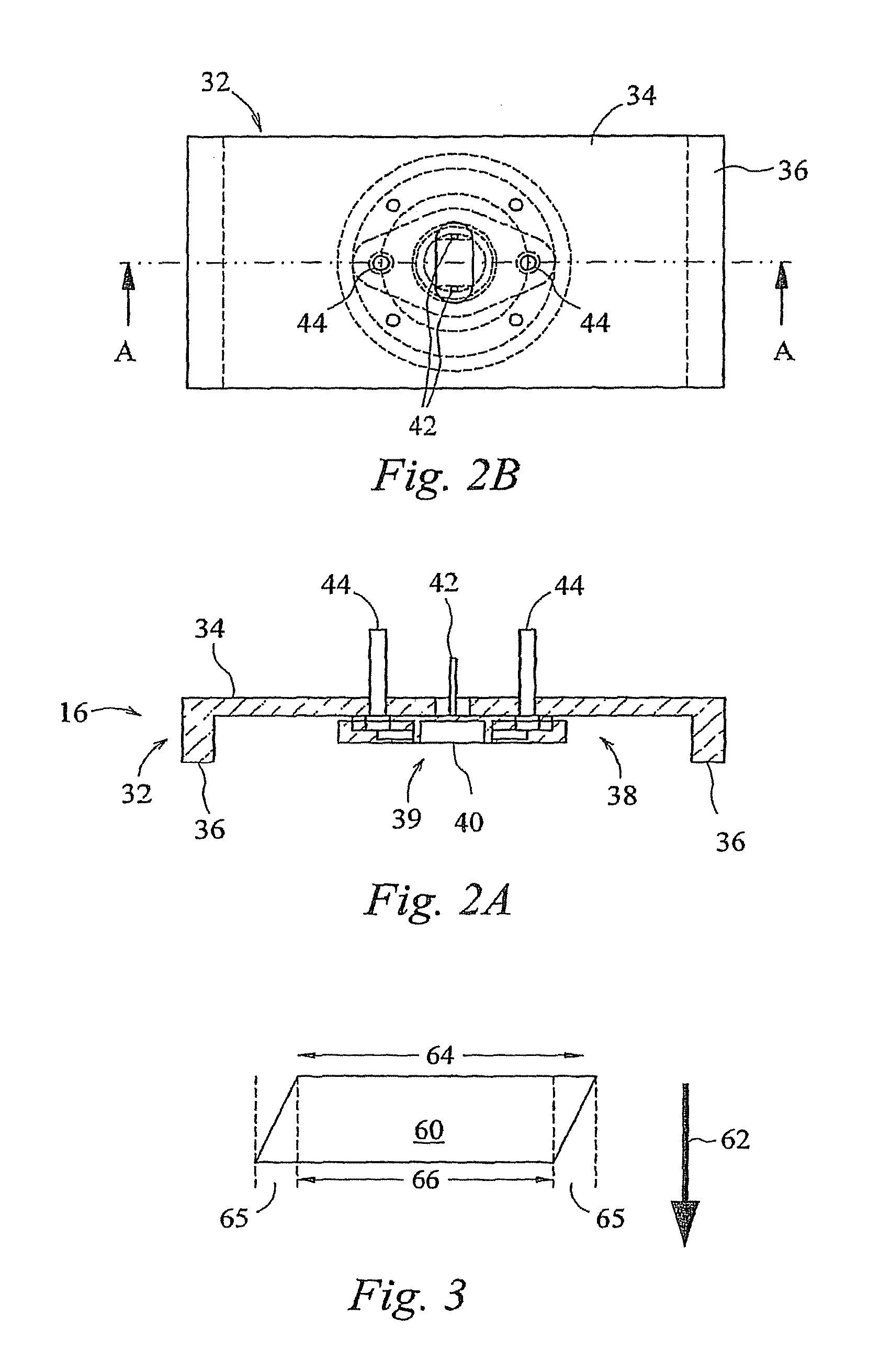
[0203]Experiments were carried out in the lab using a LED B95-66-60 source available from Roithner Lasertechnik and mounted in a housing which allowed nitrogen to be pumped through as shown in FIGS. 2a and 2b. The nitrogen source used was a HNG3-4B available from Hankison International. The use of such a source has the advantage that there is no net nitrogen liberated in the area of the printer, and that there is no need for a supply of bottled gas.

[0204]Such an arrangement did leave some residual oxygen in the nitrogen output, but it was found that the level of residual oxygen was low enough (<1%) to allow full cure of the ink using the conditions below:

[0205]

InksSericol UviJet ink (cyan, magenta,yellow and black)- a free radicalcuring inkLED Input power18 V 300 mAPeak emission405 nmNitrogen flow rate0.18 m3 / hrSpeed of curing assemblyI. Om / s relative to the substrateInk laydown on substrate18 g / m2

[0206]The arrangement was found to give full c...


PUM

PropertyMeasurementUnit
widthaaaaaaaaaa
wavelengthsaaaaaaaaaa
wavelengthaaaaaaaaaa

Abstract

A method of curing radiation-curable fluid is described. In one example, the method includes emitting radiation from an array of light-emitting diodes towards ink to be cured. LEDs are cheap, light weight, highly efficient in their conversion of electrical power, and give effectively instant switching to full power. Another advantage is that the emission spectrum of an LED is sharply peaked around the nominal frequency. Thus LEDs give several advantages over conventional radiation sources such as mercury lamps. A low oxygen environment is preferably provided at the radiation source to accelerate the curing reaction. Also described are inks which are specially formulated to respond to the radiation emission spectrum of an LED.

Description

CROSS-REFERENCE TO RELATED APPLICATIONS[0001]This is a divisional application of U.S. Ser. No. 10 / 540,130 filed Oct. 26, 2006 which is a national phase application of PCT / GB2003 / 005619 filed Dec. 22, 2003, claiming priority to Great Britain Application Nos. 0229825.5 filed Dec. 20, 2002 and PCT / GB03 / 002834 filed Jul. 1, 2003, all of which are incorporated by reference in their entirety herein.BACKGROUND OF THE INVENTION[0002]The invention relates to curing. The invention finds particular application in the curing of ink, in particular the curing of radiation-curable inks. Preferred examples of the invention relate to UV curing. Particularly preferred examples of the invention relate to the curing of ink jet inks, in particular UV curable ink jet ink. Other aspects of the invention relate to ink compositions.[0003]While embodiments of the invention described herein relate to ink, which is used to print a graphic image, the invention has general applicability to other curable fluids, ...

Claims


Application Information

Patent Timeline
Patent Type & Authority Patents(United States)
IPC IPC(8): B41J2/01B41J2/45B41M7/00
CPCB41J11/002B05D3/067B41M7/0081B41J11/00214
Inventor VOSAHLO, JINDRICHNOUTARY, CAROLE
Owner AGFA NV
Why Eureka
Try Eureka