Manufacturing method of metal product and metal product

a manufacturing method and metal technology, applied in the direction of magnetic materials, magnetic bodies, transportation and packaging, etc., can solve the problems of high cost, high cost, and high cost of metal products, and achieve the effect of high densification of the metallographic structure, small air gap rate of press-molded powder compacts, and secure the shape-keeping strength of powder compacts

Inactive Publication Date: 2013-05-14
SUNREX IND +2
View PDF12 Cites 15 Cited by
  • Summary
  • Abstract
  • Description
  • Claims
  • Application Information

AI Technical Summary

Benefits of technology

[0022]According to the aforementioned means (1), the air gap rate of the press-molded powder compact can be made small. This is because of using powder material of a unique configuration and condition produced by fracturing the metal fracture material by means of high-velocity gas swirling flow of jet mill, namely, the random amorphous flaky metal fine powder. In addition, even if the use amount of the binder is little, or even if not using the binder, the shape-keeping strength of the powder compact can be secured.
[0023]Thus, it is possible to realize the high densification of the metallographic structure, which is difficult to be realized in the conventional powder metallurgy, and for example, the metal product having high mechanical strength, particularly high impact resistance property can also be manufactured by the powder metallurgy.
[0024]According to the aforementioned means (2), in addition to the above-described advantage, homogeneity of the metallographic structure can be significantly improved.
[0025]According to the aforementioned means (3), despite being the powder metallurgical product, the metal product with fine metallographic structure and excellent in properties such as mechanical strength can be provided.
[0026]According to the aforementioned means (4), the amorphous flaky metal fine powders, which are mixed / dispersed as the sub-materials, are deformed or shaped so as to fill the air gap between particles of the spherical particulate metal powders, being the main materials. Therefore, the press-molded powder compact can obtain a high shape keeping strength, thereby hardly generating a break and a crack even if a little use amount of the binder or not using the binder.
[0027]According to the aforementioned (5), the spherical particulate metal powder forms a framework structure in a three-dimensional network (or lattices), and the metallographic structure, with the amorphous flaky metal fine powder filled in the air gap of this framework structure is formed. Thus, the metal product having the advantage of the powder metallurgy such as high rigidity and the impact resistance which is not obtained by the conventional powder metallurgy can be obtained. In addition, a sintered metal product with fine metallographic structure which is not obtained by the conventional powder metallurgy can be obtained.

Problems solved by technology

However, a powder metallurgy process is frequently used, in which a metal powder (powder) is used as a metal material, and a powder compact is obtained by press-molding this metal powder and thereafter this powder compact is heated and sintered, for the metal product having a precise and complicated shape or the metal product requiring a particular material characteristic like a magnetic component.

Method used


Image

  • Manufacturing method of metal product and metal product
  • Manufacturing method of metal product and metal product
  • Manufacturing method of metal product and metal product

Examples


embodiment 1

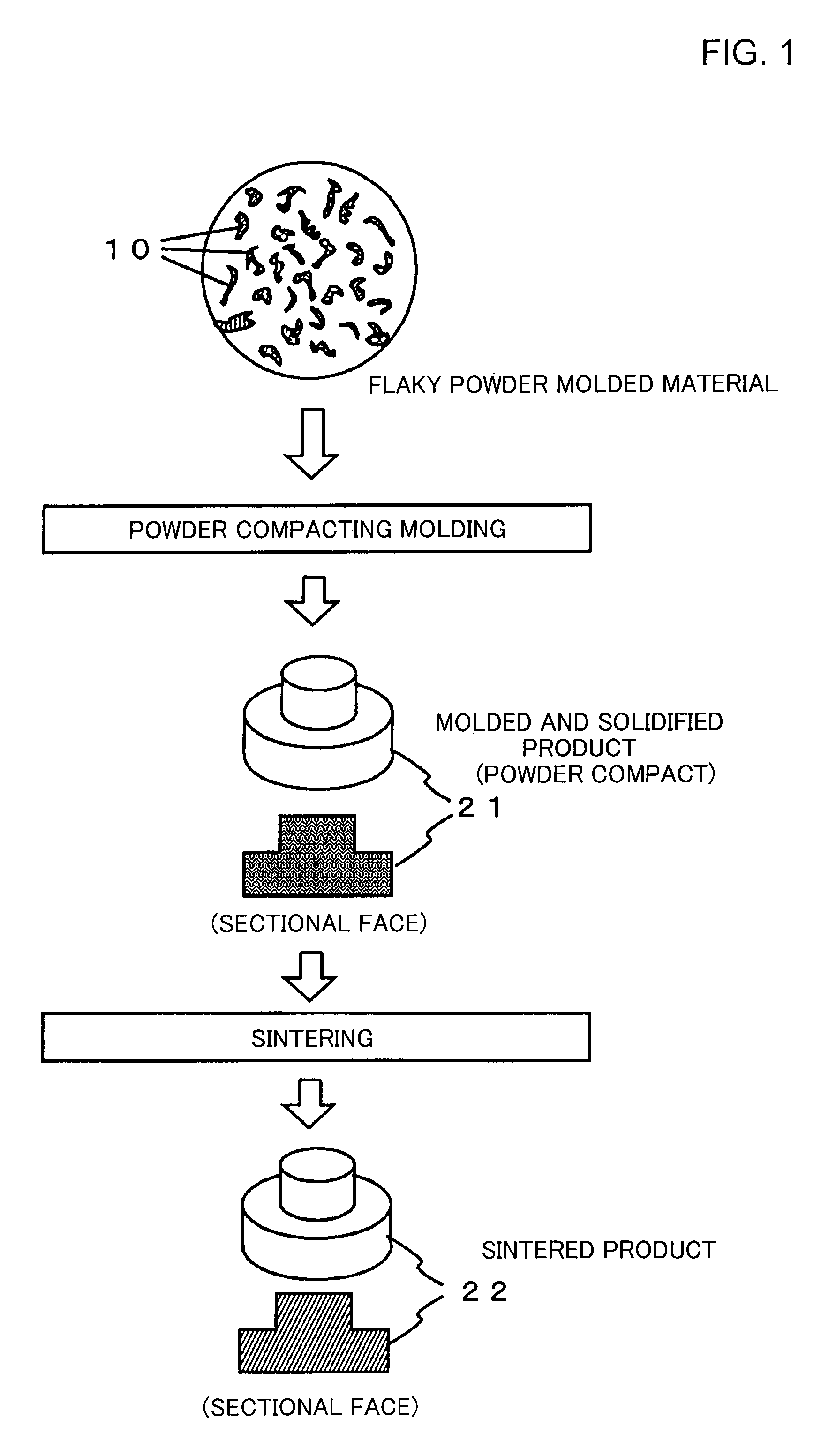
[0030]FIG. 1 is a view schematically showing the step of a manufacturing method of a metal product according to a first embodiment of the present invention. The present invention provides the manufacturing method of the metal product in which the metal powder is pressure-molded into a given configuration, and thereafter the air gap between the powder particles of the molded material is fusion-bonded by sintering, and the metal product. The metal powder used here has properties as will be described below.

[0031]Namely, as shown in this figure, in the first embodiment of the present invention, a metal fine powder 10 fractured by a jet mill is used as the metal powder, being the molded material. The jet mill performs fracture of a metal fracture material by an impact of fracture materials by means of high velocity gas swirling flow.

[0032]By this fracture, for example as schematically and expandedly shown in this figure, an amorphous flaky metal fine powder 10 with random configuration i...

embodiment 2

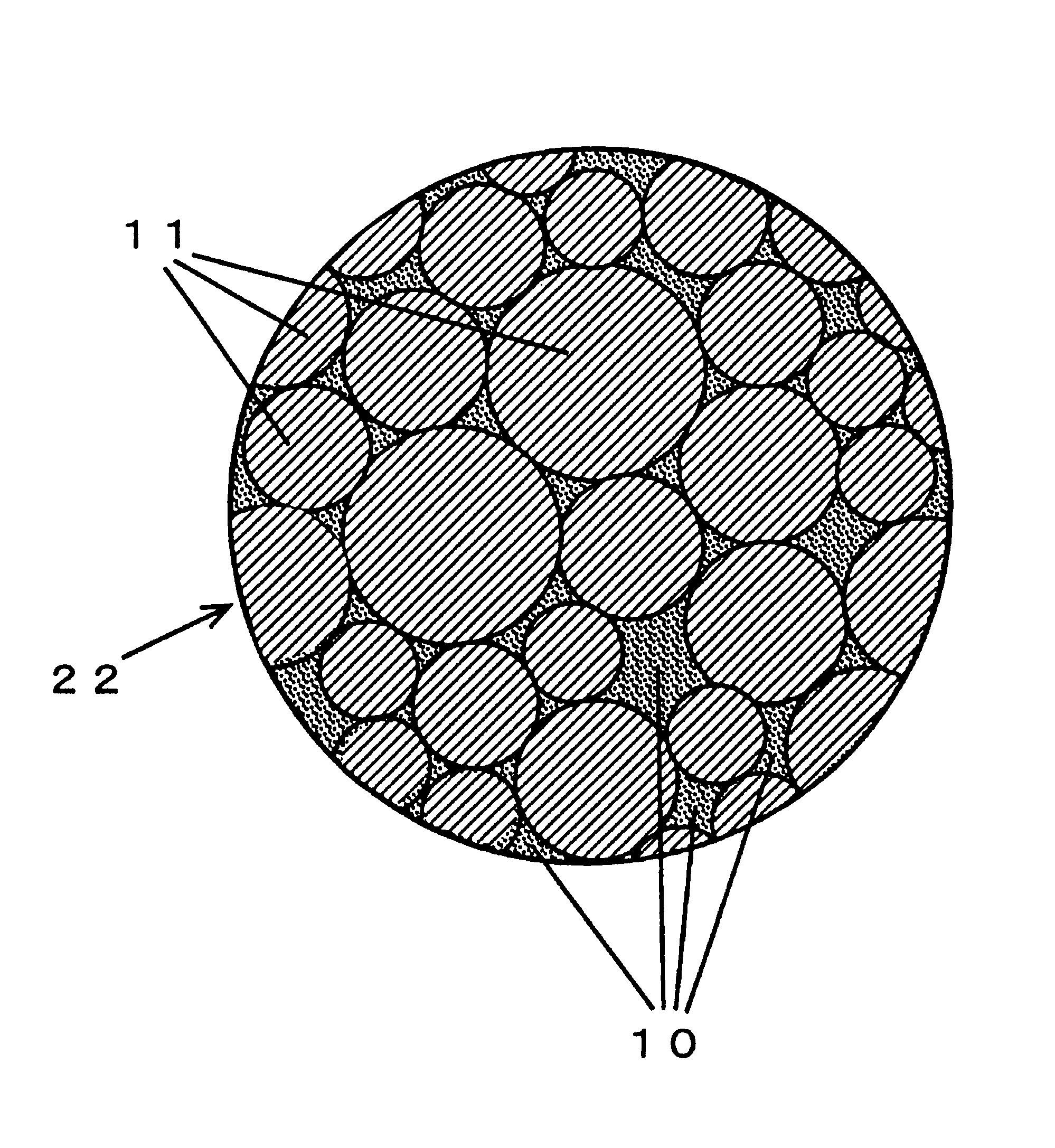
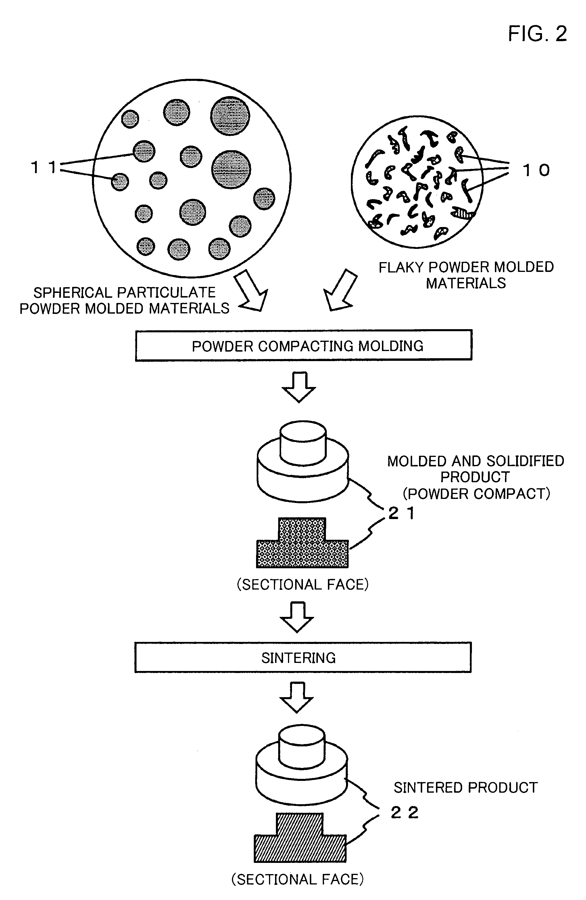
[0039]FIG. 2 is a rough step view schematically showing the manufacturing method of the metal product by the second embodiment. In this second embodiment, a spherical particulate metal powders 11 obtained by an atomizing method are used as main materials, and a random amorphous flaky metal fine powders 10 having a finer particle size than the metal powders 11 and produced by fracturing the metal fracture material by means of high-velocity gas swirling flow are used as sub-materials, and molding and sintering are performed in a state of dispersing the sub-materials (10) in the main materials (11).

[0040]In the step shown in this figure, the sub-materials consisting of the amorphous flaky metal powders 10 are mixed and dispersed in the main materials consisting of the spherical particulate metal powders 11 at a prescribed ratio, and a mixture material thus obtained is molded into the powder compact 21 of a given configuration by press-molding (pressure molding) using a die.

[0041]At thi...


PUM

PropertyMeasurementUnit
particle sizeaaaaaaaaaa
mixing ratioaaaaaaaaaa

Abstract

In sintering a metal powder after pressure molding into a given configuration, random amorphous flaky metal fine powders (10) are used as metal powder materials. In addition, spherical particulate metal powders 11 are used as main materials, and random amorphous flaky metal fine powders 10 having finer particle size than the metal powders 11 and produced by fracturing a metal fracture material by means of high-velocity gas swirling flow are used as sub-materials, and molding and sintering are performed in a state of dispersing the sub-materials (10) in the main materials (11). Thus, despite being a power metallurgical product, it is possible to obtain a metal product having a dense metallographic structure and excellent in properties such as mechanical strength.

Description

TECHNICAL FIELD[0001]The present invention relates to a manufacturing method of a metal product obtained by molding and sintering a metal powder into a given configuration and the metal product.BACKGROUND ART[0002]As a method of manufacturing the metal product of a given configuration, the method of casting, forging, rolling, and machining, etc are given as examples. However, a powder metallurgy process is frequently used, in which a metal powder (powder) is used as a metal material, and a powder compact is obtained by press-molding this metal powder and thereafter this powder compact is heated and sintered, for the metal product having a precise and complicated shape or the metal product requiring a particular material characteristic like a magnetic component.[0003]In this powder metallurgy, the metal powder with a particle size of 1 μm to 100 μm manufactured by an atomizing method is mainly used (see patent document 1). The metal powder manufactured by the atomizing method has a p...

Claims


Application Information

Patent Timeline
Patent Type & Authority Patents(United States)
IPC IPC(8): B22F9/20B22F1/068
CPCB22F1/0055B22F2009/044B22F2998/00B22F2998/10B22F2999/00Y10T428/12014B22F9/002B22F9/04B22F3/02B22F3/10B22F1/068
Inventor ITO, KENZOYAMAMOTOYAMAMOTO, ETSUO
Owner SUNREX IND
Why Eureka
Try Eureka