
Process for the treatment of wastes combining a phase of treatment by methanization and a phase of thermophilic aerobic treatment

a technology of methanization and waste, applied in the field of organic liquid and solid waste treatment, can solve the problems of increasing the risk of infectious agents, difficult sorting, and serious pollution of surface water and groundwater

Inactive Publication Date: 2013-05-21
SOC CIV DLMR
View PDF11 Cites 0 Cited by
  • Summary
  • Abstract
  • Description
  • Claims
  • Application Information

AI Technical Summary

Benefits of technology

The invention relates to a method for treating polluted air by using it to supply oxygen to a biogas combustion device. This process avoids creating residues or odors that require expensive reprocessing and reduces the need for external treatment units. The treatment unit is self-sufficient in energy, efficient in relation to the volume of waste and compact due to the proximity of different resources used within the same device.

Problems solved by technology

Indeed, it is well known that if organic wastes are not disposed of appropriately, simply sending them to landfill can lead to serious pollution of surface water and groundwater, and increase the risk of infectious agents.
However, as regards the treatment of organic waste, sorting is difficult as both the sources and the type of waste are multiple: waste water, household waste, agri-foodstuffs industrial waste, green waste originating from the upkeep of open spaces, runoff water, etc.
Generally, organic wastes are collected separately, most frequently via the sewer system, and the problem arises mainly in terms of the volume and heterogeneity of the substrates requiring treatment.
These conditions limit the volumes which can be treated, as in addition to containment, there is the time required for decomposition of the waste, which is approximately from a few days to several weeks, according to the volume and quality of the substrate.
This type of installation requires substantial engineering investment, which is justified by the need to extract the underground gases from the landfill sites, which are greenhouse gases, presenting risks of explosion or soil contamination.
These investments greatly exceed the proceeds of the sale of biogas to industry or even to consumers.
For reasons of productivity of this system, decomposition of the organic matter cannot be completed in the digester.
Methanization units on a smaller scale do exist, for example for producing biogas from pig slurry, but these do not operate continuously.
Whatever the type of installation, it must be emphasized that the biogas produced by methanization is saturated with water and that it comprises other gases apart from methane, which are potentially dangerous.
The biogas must therefore undergo treatment or enrichment steps to allow it to be sold, which currently makes its production uneconomic.
Under these high-temperature conditions, most of the active substances that can cause safety inconvenience in the recycling of organic wastes, such as medicines—including antibiotics—, synthetic hormones, pesticides, detergents and toxins, are mostly digested or destroyed.
Firstly, it requires a considerable input of external energy, due to the need to bring a large volume of waste up to a temperature of around 50° C. This constraint requires heating installations which are not present in the conventional aerobic treatment systems operating at ambient temperature. In addition to the energy required for their operation, these installations impose an extra cost which is deemed excessive in relation to the productivity gain.
Secondly, activation of the fermentation requires an active supply of air having a sufficient oxygen content, which is generally pumped in at the base of the fermentation tanks. Finally, these are considerable volumes of air which have to come into contact with the microorganisms and which are then dispersed into atmospheric air. This air, which can be classified as contaminated, comprises malodorous effluvia which represent a genuine nuisance for residents living near this type of installation.
Thirdly, the wastes treated at the outlet of the tanks must preferably be dehydrated in order to be able to be transported under correct conditions, which, again, increase the energy consumption of this system.

Method used


Image

  • Process for the treatment of wastes combining a phase of treatment by methanization and a phase of thermophilic aerobic treatment
  • Process for the treatment of wastes combining a phase of treatment by methanization and a phase of thermophilic aerobic treatment

Examples


example

Device According to the Invention in the Form of a Self-Sufficient Modular Treatment Unit

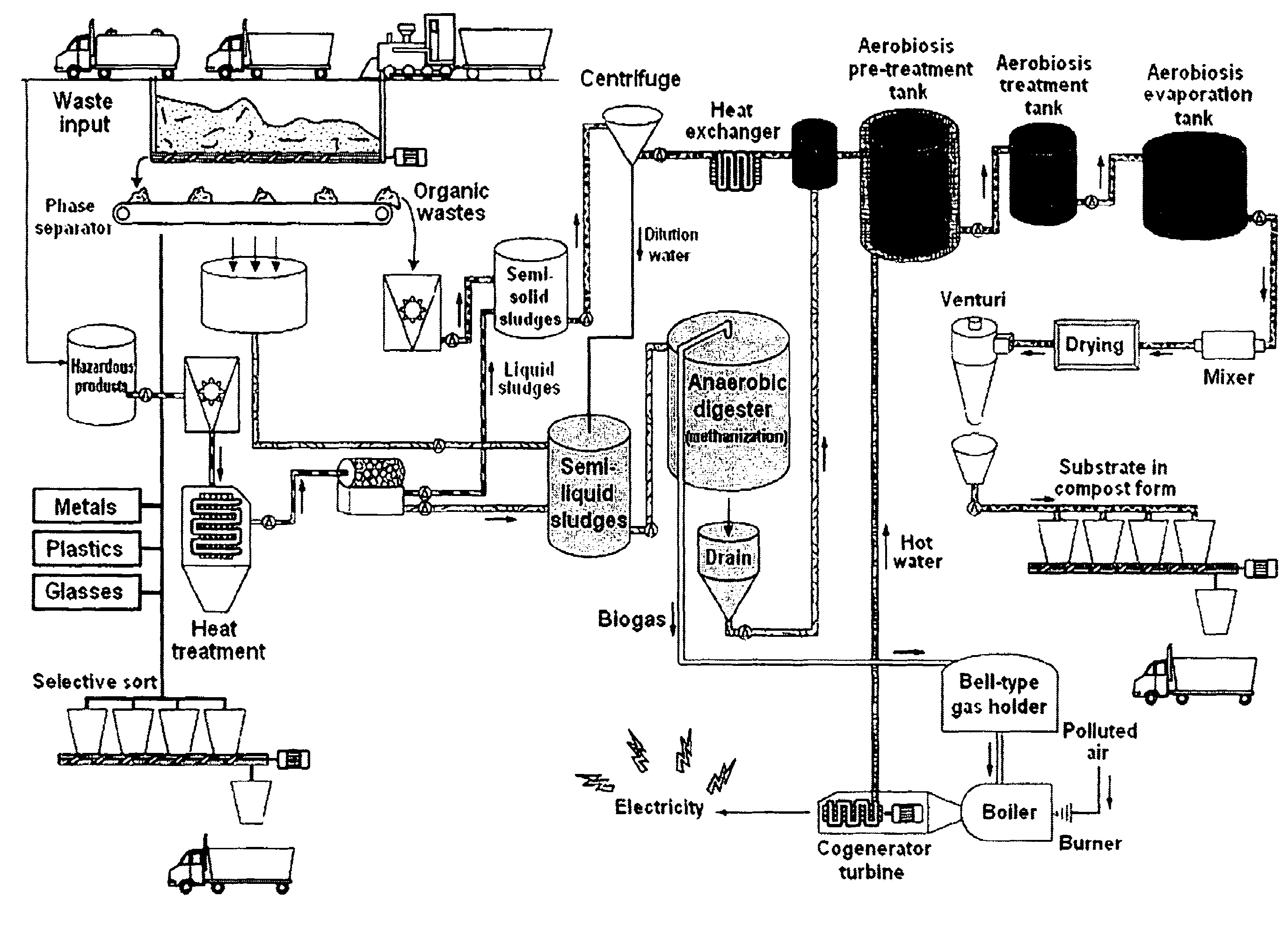
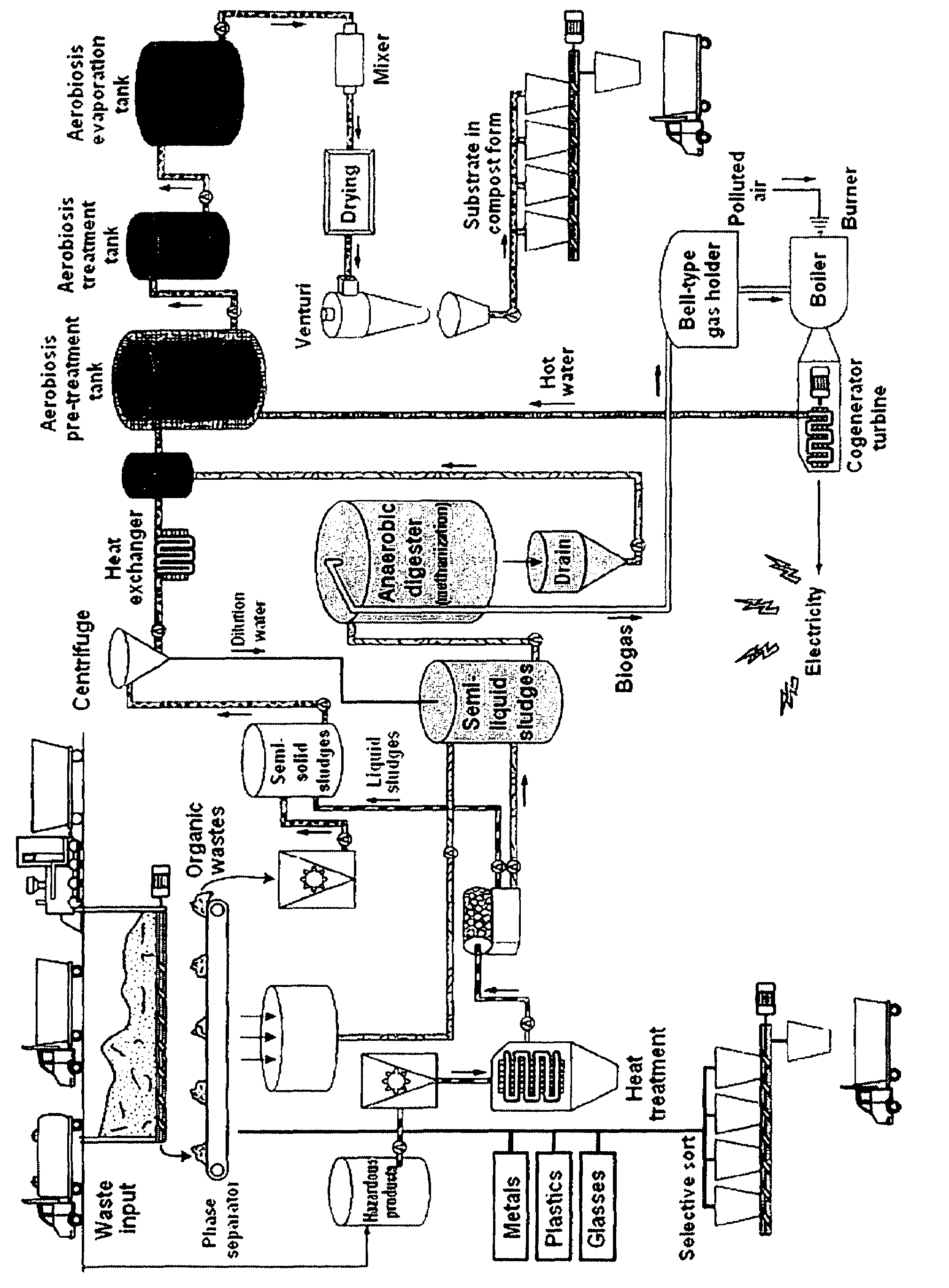
[0093]The treatment unit comprises an intake through which the untreated organic wastes in solid and liquid form are introduced into the enclosure of the self-sufficient treatment unit. Using a phase separator, the liquid wastes are separated from the more solid wastes. The solid wastes undergo manual sorting on a conveyor belt in order to remove those which cannot be crushed. Wastes of this kind, such as for example pieces of wood, are incinerated in the boiler where the biogas is burned. The other wastes are crushed then transferred on a conveyor belt to a first tank of the thermophilic or mesophilic aerobic phase treatment unit, where they are stored. This first tank has a capacity of approximately 110 m3. The liquid wastes are recovered by gravity at the level of a collector which opens out into a digester. The digester is in the form of a cylindrical tank having a capacity of approximately ...


PUM

PropertyMeasurementUnit
temperatureaaaaaaaaaa

Abstract

The present invention relates to the treatment of organic liquid and solid waste, comprising a first stage of treatment of the liquid content fraction of the waste by methanization, a second stage of treatment in a thermophilic or mesophilic aerobic phase of the semi-solid content fraction of the waste and a third stage in which said treated liquid and solid content portions are mixed in order to form a substrate, which is further treated by mesophilic or thermophilic aerobic phase treatment, resulting into compost.

Description

CROSS REFERENCE TO RELATED APPLICATIONS[0001]This application is entitled to the benefit of and incorporates by reference essential subject matter disclosed in International Patent Application No. PCT / IB2008 / 003670 filed on Nov. 27, 2008; French Patent Application No. 0759375 filed Nov. 28, 2007; and U.S. Provisional Application Ser. No. 61 / 019,034 filed Jan. 4, 2008.FIELD OF THE INVENTION[0002]The present invention relates to the treatment of organic liquid and solid waste, comprising a first stage of treatment of the liquid content fraction of the waste by methanization, a second stage of treatment in a thermophilic or mesophilic aerobic phase of the semi-solid content fraction of the waste, and a third stage in which said treated liquid and solid content portions are mixed in order to form a substrate, which is further treated by mesophilic or thermophilic aerobic phase treatment, resulting into compost.BACKGROUND OF THE INVENTION[0003]With increasing population, disposal of orga...

Claims


Application Information

Patent Timeline
Patent Type & Authority Patents(United States)
IPC IPC(8): C02F3/30
CPCB09B3/00C05F17/0027C05F17/0294C12M23/58C12M43/08C12M45/02C12M45/04C12M21/04C02F11/04Y02E50/343Y02W10/30Y02P20/145C05F17/957C05F17/50Y02E50/30Y02W10/20Y02W30/40
Inventor LEMAIRE, PIERREDE LIPPE, BEATRICERANKE, FRITZMARTIN, DOMINIQUE
Owner SOC CIV DLMR
Learn More