Switched safety protection circuit for an AIMD system during exposure to high power electromagnetic fields

a safety protection circuit and electromagnetic field technology, applied in the field of energy induced on implanted leads, can solve the problems of insufficient predictiveness of sar level, latent problems of cardiac pacemakers, and inability to integrate magnetic resonance imaging (mri) into active implantable medical devices,

Inactive Publication Date: 2013-05-21
WILSON GREATBATCH LTD
View PDF276 Cites 17 Cited by
  • Summary
  • Abstract
  • Description
  • Claims
  • Application Information

AI Technical Summary

Benefits of technology

[0045]The diversion circuit may also comprise a high pass filter which prevents low frequency gradient field-induced energy in the implanted lead or the leadwire from passing through the diversion circuit to the energy dissipating surface. The high pass filter may comprise a resistor in series with a capacitor or an L-C trap filter.

Problems solved by technology

Compatibility of probes, catheters, cardiac pacemakers, implantable defibrillators and other types of active implantable medical devices with magnetic resonance imaging (MRI) and other types of hospital diagnostic equipment has become a major issue.
There have been reports of latent problems with cardiac pacemakers or other AIMDs after an MRI procedure sometimes occurring many days later.
Moreover, there are a number of recent papers that indicate that the SAR level is not entirely predictive of the heating that would be found in implanted leads or devices.
It is speculated that SAR level alone is not a good predictor of whether or not an implanted device or its associated leadwire system will overheat.
These antennas are not very efficient due to the damping effects of body tissue; however, this can often be offset by extremely high power fields (such as MRI pulsed fields) and / or body resonances.
Subjected to RF frequencies, the lead itself can exhibit complex transmission line behavior.
The effects of this heating are not readily detectable by monitoring during the MRI.
Such long term heating effects of MRI have not been well studied yet for all types of AIMD leadwire geometries.
There can also be localized heating problems associated with various types of electrodes in addition to tip electrodes.
While these anecdotal reports are of interest, they are certainly not scientifically convincing that all MRI can be safe.
For example, just variations in the pacemaker leadwire length can significantly affect how much heat is generated.
Most experts still conclude that MRI for the pacemaker patient should not be considered safe.
It is well known that many of the undesirable effects in an implanted lead system from MRI and other medical diagnostic procedures are related to undesirable induced EMFs in the lead system and / or RF currents in its distal tip (or ring) electrodes.
This can lead to overheating of body tissue at or adjacent to the distal tip.
This is because tissue damage in this area can raise the capture threshold or completely cause loss of capture.
For pacemaker dependent patients, this would mean that the pacemaker would no longer be able to pace the heart.
This would, of course, be life threatening for a pacemaker dependent patient.
A very important and life-threatening problem is to be able to control overheating of implanted leads during an MRI procedure.
A major challenge for designing an L-C bandstop filter for human implant is that it must be very small in size, biocompatible, and highly reliable.
As the feedthrough capacitor charges up this voltage fall can create one of two problems.
First, the voltage induced on the leadwire system could directly capture the heart thereby creating a dangerously rapid heart rate which could then result in a dangerous ventricular arrhythmia.
For example, ventricular fibrillation can result in sudden death.
Another problem associated with too high of a value of a feedthrough capacitor at the input to the AIMD is that this R-C charging circuit can cause pulses to appear at the input sense amplifier (such as a cardiac pacemaker) such that the pacemaker would oversense or falsely interpret this input as a normal heartbeat.
In certain cases this can cause a demand pacemaker to inhibit (stop pacing).
For a pacemaker dependent patient this can lead to systole and be immediately life threatening.
In fact, in many measurements made by the inventors, temperature rises of over 30 degrees C. have been reduced to less than 3 degrees C. However, a secondary problem has been discovered.
In some cases, the inventors have measured temperature rises immediately proximal to the bandstop filters, which is undesirable.

Method used


Image

  • Switched safety protection circuit for an AIMD system during exposure to high power electromagnetic fields
  • Switched safety protection circuit for an AIMD system during exposure to high power electromagnetic fields
  • Switched safety protection circuit for an AIMD system during exposure to high power electromagnetic fields

Examples


Embodiment Construction

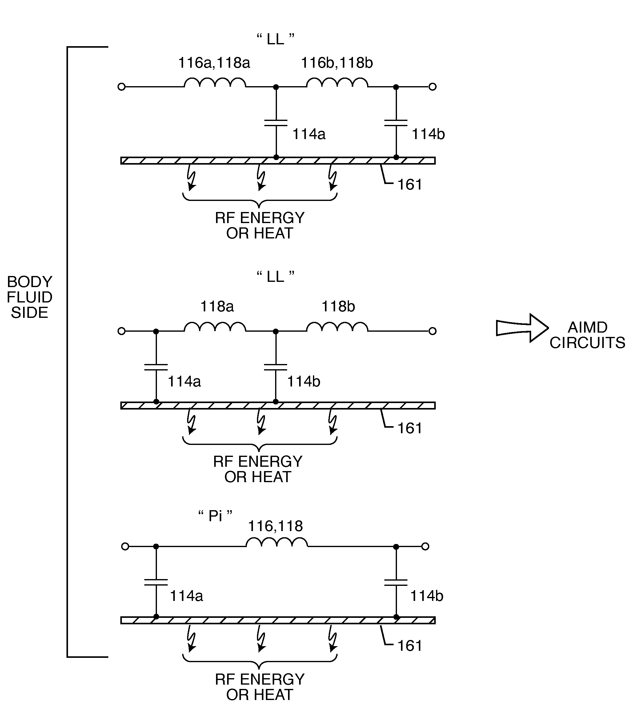
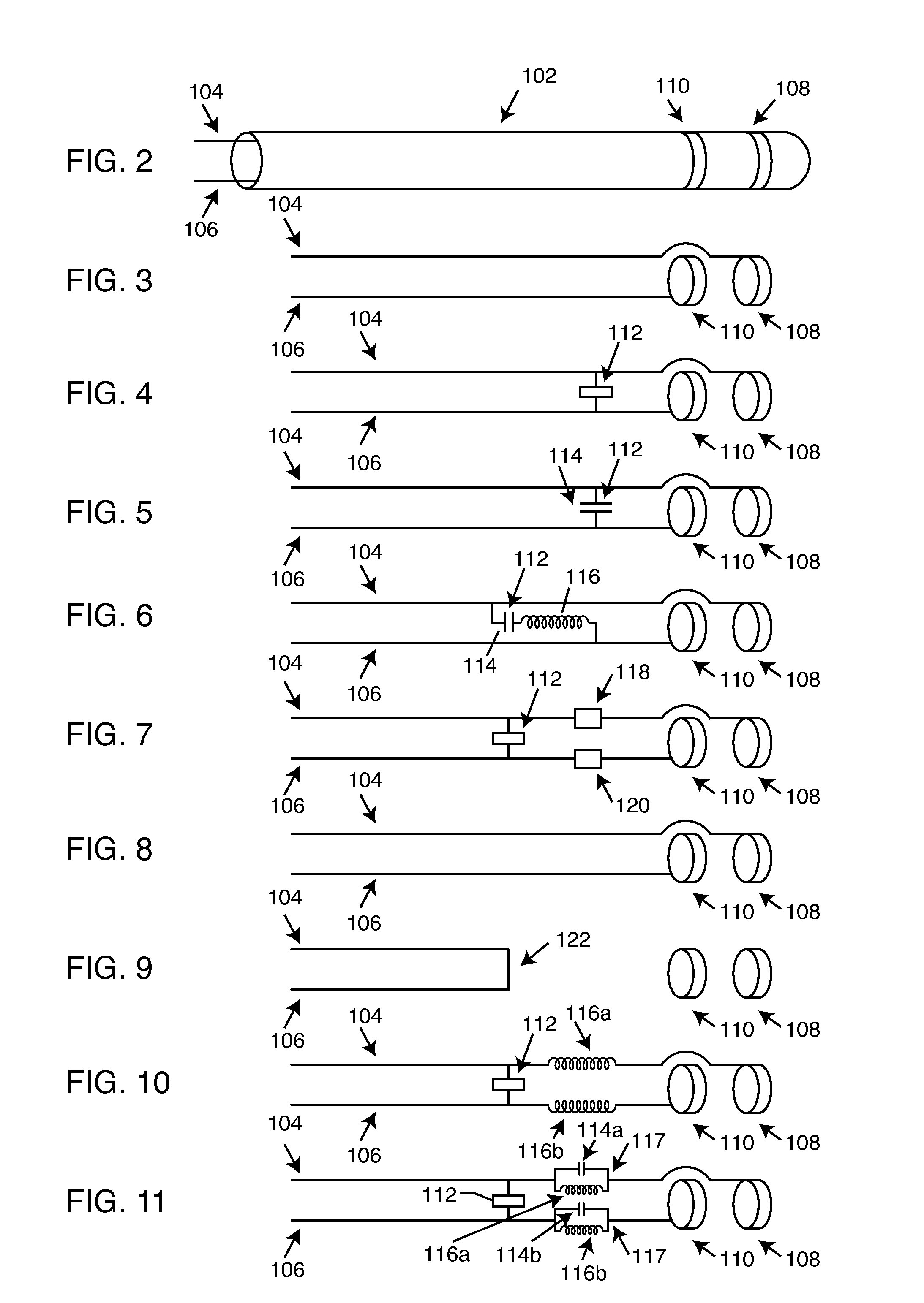
[0171]As shown in the drawings for purposes of illustration, the present invention resides in a tuned energy balanced system including a switched diverter circuit, for minimizing heating of an implanted lead in a high power electromagnetic field environment. The tuned energy balanced system comprises an implanted lead having impedance characteristics at a selected RF frequency or frequency band, and an energy dissipating surface associated with the implanted lead. An energy diversion circuit conductively couples the implanted lead to the energy dissipating surface. The diversion circuit comprises one or more passive electronic network components whose impedance characteristics are at least partially tuned to the implanted lead's impedance characteristics, to facilitate transfer to the energy dissipating surface of high frequency energy induced on the implanted lead at the selected RF frequency or frequency band.

[0172]More particularly, the present invention resides in a switched div...


PUM


Abstract

An energy management system that facilitates the transfer of high frequency energy induced on an implanted lead or a leadwire includes an energy dissipating surface associated with the implanted lead or the leadwire, a diversion or diverter circuit associated with the energy dissipating surface, and at least one switch disposed between the diversion circuit and the AIMD electronics for diverting energy in the implanted lead or the leadwire through the diversion circuit to the energy dissipating surface. The switch may comprise a single or multi-pole double or single throw switch. The diversion circuit may be either a high pass filter or a low pass filter.

Description

CROSS-REFERENCE TO RELATED APPLICATIONS[0001]This application claims priority from parent application Ser. Nos. 12 / 489,921, now U.S. Pat. No. 7,751,903.FIELD OF INVENTION[0002]This invention generally relates to the problem of energy induced on implanted leads during medical diagnostic procedures such as magnetic resonant imaging (MRI). Specifically, the radio frequency (RF) pulsed field of MRI can couple to an implanted lead in such a way that electromagnetic forces (EMFs) are induced in the lead. The amount of energy that is induced is related to a number of complex factors, but in general, is dependent upon the local electric field that is tangent to lead and the integral of the electric field strength along the lead. In certain situations, these EMFs can cause currents to flow into distal electrodes or in the electrode interface with body tissue. It has been documented that when this current becomes excessive, that overheating of said lead or its associated electrode or overheat...

Claims


Application Information

Patent Timeline
Patent Type & Authority Patents(United States)
IPC IPC(8): A61N1/08A61N1/16A61N1/375
CPCA61B5/055A61B5/7203A61B2017/00911A61B2018/00839A61N1/3718A61B2090/374A61N1/086A61N1/37512A61B5/283G01R33/285H03H7/0107H03H7/1758H03H7/1766
Inventor JOHNSON, ROBERT SHAWNDABNEY, WARREN S.STEVENSON, ROBERT A.WILLIAMS, CHRISTOPHER MICHAELMOSCHIANO, HOLLY NOELLEBRAINARD, SCOTT
Owner WILSON GREATBATCH LTD
Why Eureka
Try Eureka