Integrated terahertz antenna and transmitter and/or receiver, and a method of fabricating them

a technology of integrated terahertz and transmitters, applied in the direction of optical radiation measurement, instruments, spectrophotometry/monochromators, etc., can solve the problems of poor efficiency, difficult and expensive silicon lens positioning, and large amount of silicon, so as to achieve easy and inexpensive fabrication, the effect of little dispersion

Active Publication Date: 2013-05-28
CENT NAT DE LA RECHERCHE SCI
View PDF3 Cites 12 Cited by
  • Summary
  • Abstract
  • Description
  • Claims
  • Application Information

AI Technical Summary

Benefits of technology

[0013]In particular, an object of the invention is to provide an antenna for transmitting or receiving terahertz radiation that presents greater efficiency than the planar antennas presently in use.
[0014]Another object of the invention is to provide a terahertz antenna that is easy and inexpensive to fabricate, even in mass production.
[0015]Another object of the invention is to provide a terahertz antenna that is very broadband and that presents little dispersion. Such an antenna can be suitable for use under pulse conditions using pulses that are very short (picoseconds), and also under continuous conditions, possibly tunable conditions.

Problems solved by technology

Firstly, making the lens out of silicon and positioning it on the substrate with accuracy of micrometer order relative to the antenna is very difficult and expensive.
Secondly, the use of a coupling lens is essential in order to prevent the radiation that is emitted mainly into the semiconductor substrate becoming trapped therein. In spite of the presence of such a lens, only about 21% of the power emitted by a planar type antenna is actually radiated into empty space, with the remainder being trapped and absorbed by the substrate.
Furthermore, the planar antenna in the most widespread use, a Hertz dipole, presents poor efficiency and, worse, its efficiency depends strongly on frequency.
However their poor efficiency makes them unsuitable for use under continuous conditions, where the powers involved are very small.
The results obtained with the help of such an antenna are not entirely satisfactory, in particular from the points of view energy efficiency and large dispersion of pulses.
Such an antenna presents relatively good efficiency and is a broadband antenna, but it is highly dispersive.
Consequently, it is not suitable for use under pulse conditions.
Nevertheless, the solutions provided by those methods are not satisfactory because of the cost and the complexity of the fabrication methods and because of the fragility of the resulting structures.
In addition, the techniques used (deep etching, dielectric membrane, etc.) are appropriate essentially for silicon, a material that is not particularly suitable for terahertz applications.

Method used


Image

  • Integrated terahertz antenna and transmitter and/or receiver, and a method of fabricating them
  • Integrated terahertz antenna and transmitter and/or receiver, and a method of fabricating them
  • Integrated terahertz antenna and transmitter and/or receiver, and a method of fabricating them

Examples


Embodiment Construction

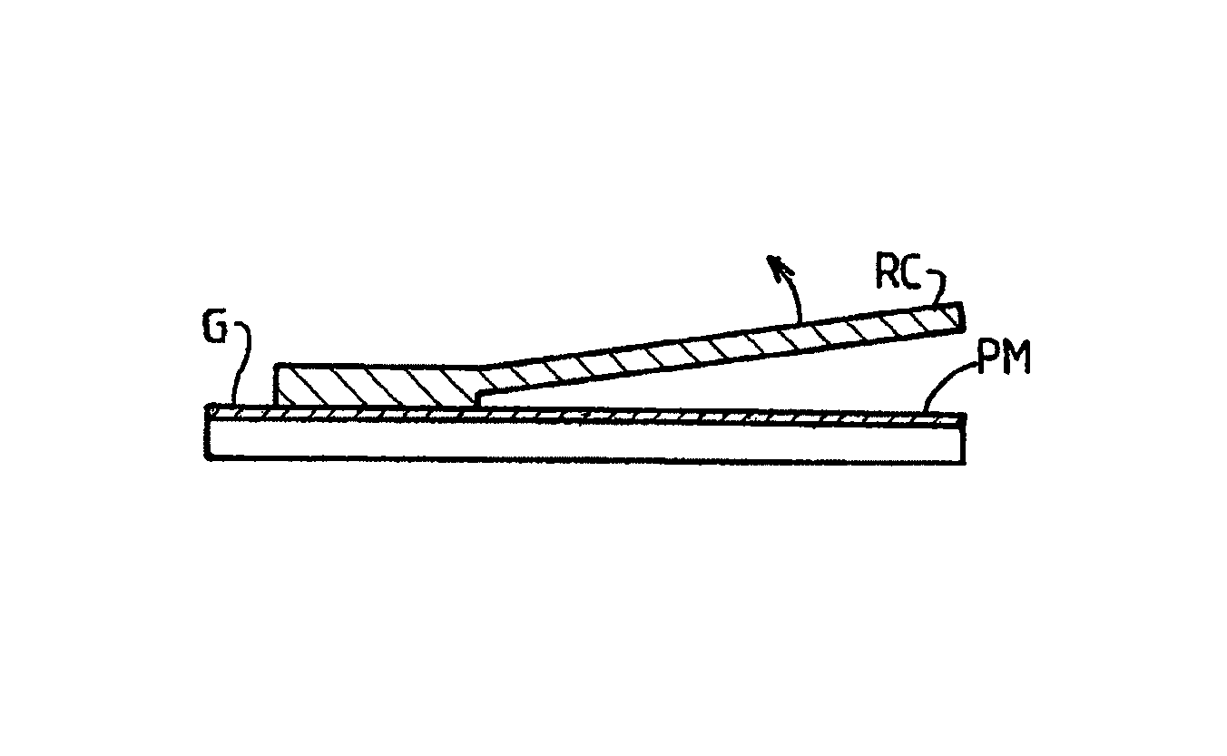
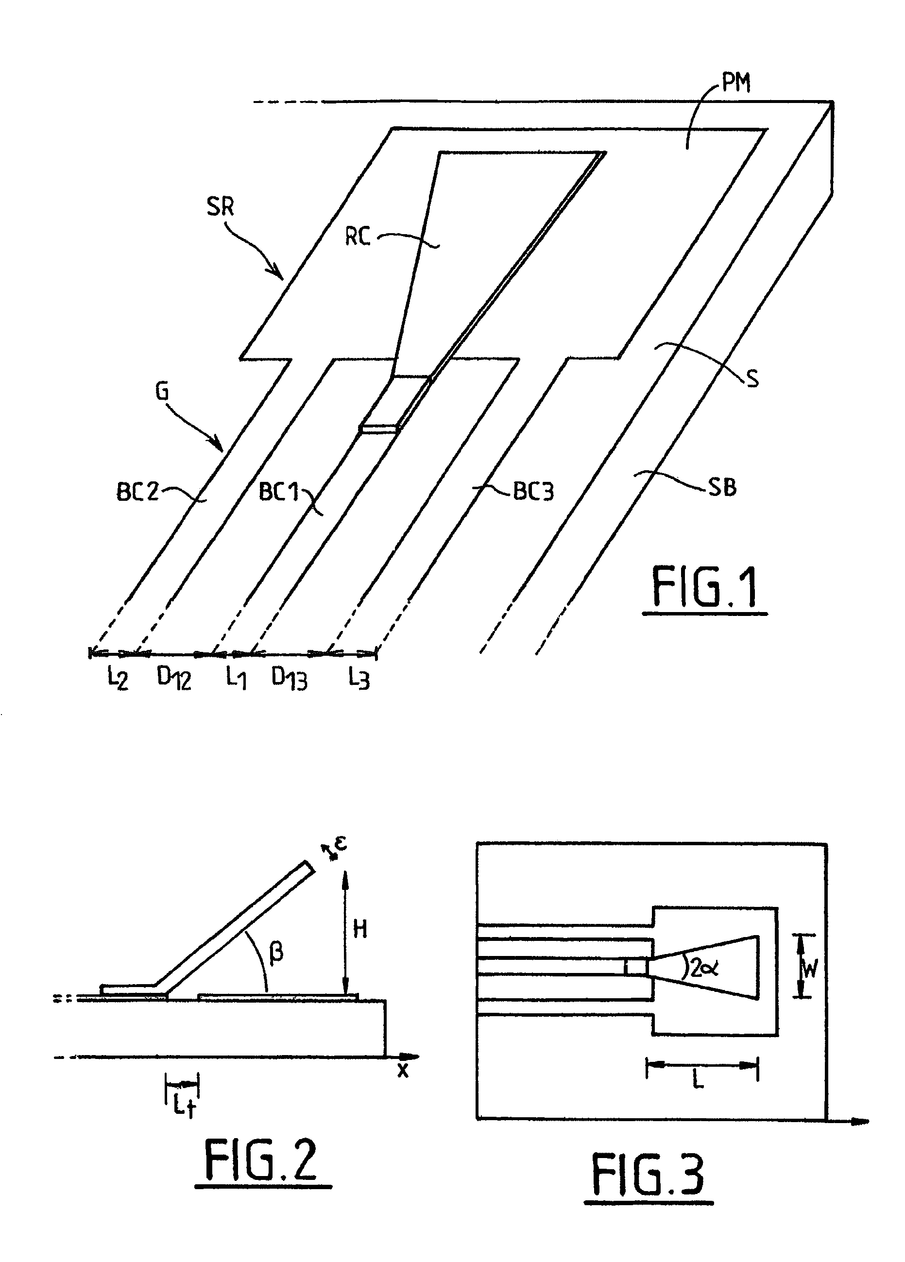
[0047]Whereas the integrated antennas that operate in the terahertz range and that are known in the prior art are mainly of the planar type, the invention relates to a three-dimensional antenna made on an insulating or semiconductor substrate using standard photolithographic techniques. More precisely, the antenna is of the transverse electromagnetic wave horn type, i.e. it is constituted by a flared waveguide made up of two superposed conductive sheets separated by an angle β.

[0048]In the embodiment shown in FIGS. 1 to 3, the two conductive sheets constituting the transverse electromagnetic wave horn comprise a ground plane PM deposited on a surface S of an insulating or semiconductor substrate SB, and a conductive ribbon RC extending above said ground plane and forming an angle β therewith. The ribbon RC is substantially plane and of triangular shape with an angle at the apex of 2α. The ground plane PM and the ribbon RC form a waveguide of impedance that is constant along the long...


PUM


Abstract

An integrated antenna for transmitting or receiving radiation in a frequency range from 100 GHz to 3 THz, the antenna being characterized in that it comprises: a conductive ground plane (PM) deposited on a “top” surface (S) of a dielectric or semiconductor substrate (SB); a conductive ribbon (RC) extending above said ground plane (PM) and forming an angle (β) therewith, so as to form a radiating structure (SR) of the transverse electromagnetic wave horn type; and a planar waveguide (G) comprising at least first and second conductive strips (BS1, BS2) formed on said top surface of the substrate, and connected respectively to said conductive ribbon (RC) and to said conductive ground plane (PM). A terahertz transmitter and / or receiver including such an antenna and a device for generating and / or detecting a terahertz signal integrated on the same substrate (SB) as the antenna and connected thereto by said waveguide (G). A method of fabricating such an antenna and such a transmitter and / or receiver.

Description

CROSS REFERENCE TO RELATED APPLICATIONS[0001]This application is a national stage application filed under 35 U.S.C. 371 of International Application No. PCT / FR2007 / 001912, filed Nov. 21, 2007, which claims priority to French Application No. 06 10164, filed Nov. 21, 2006.FIELD AND BACKGROUND OF THE INVENTION[0002]The invention relates to an integrated antenna for transmitting and / or receiving terahertz radiation, and to a transmitter and / or receiver device for terahertz radiation including such an antenna, and also to a method of fabricating said antenna and said device.[0003]The term “terahertz” radiation covers electromagnetic radiation at a frequency lying in the range 100 gigahertz (GHz) to 3 terahertz (THz) approximately (1 THz=1012 hertz (Hz)=1000 GHz). In a more restrictive sense, terahertz radiation is taken as being synonymous with submillimetric radiation, i.e. radiation having a wavelength lying in the range 100 micrometers (μm) to 1 millimeters (mm) approximately (approxi...

Claims


Application Information

Patent Timeline
Patent Type & Authority Patents(United States)
IPC IPC(8): G01J3/28H01Q13/00
CPCH01Q1/38H01Q13/08H01Q13/12H01S1/02G02F1/3534G02F2203/13
Inventor LAMPIN, JEAN-FRANCOIS FERNANDPEYTAVIT, EMILIEN PASCAL
Owner CENT NAT DE LA RECHERCHE SCI
Why Eureka
Try Eureka