Non-contact electric power transmission circuit

a transmission circuit and non-contact technology, applied in the direction of electric variable regulation, process and machine control, instruments, etc., can solve the problems of increased radiation noise, inability to achieve closed-loop feedback signal, and general phase shift control method not suitable for non-contact electric power transmission circuits. achieve the effect of high efficiency

Inactive Publication Date: 2013-06-11
MURATA MFG CO LTD
View PDF17 Cites 17 Cited by
  • Summary
  • Abstract
  • Description
  • Claims
  • Application Information

AI Technical Summary

Benefits of technology

[0011]The aspect of the invention provides the non-contact electric power transmission circuit in which the resonant type full bridge circuit can be controlled by the push-pull output PWM control at a level similar to that of the phase shift operation. Therefore, the switching element having the small withstand voltage can be selected to implement the low-cost, high-efficiency non-contact electric power transmission circuit. A measure against noise can easily be performed. The small switching element is used, so that the compact non-contact electric power transmission circuit can be implemented.

Problems solved by technology

Because the vibration of the voltage increases an unnecessary radiation noise, disadvantageously it is necessary to use a switching element having a high withstand voltage.
Therefore, the general phase shift control method is not suitable for the non-contact electric power transmission circuit in which the closed-loop feedback signal is hardly obtained.

Method used


Image

  • Non-contact electric power transmission circuit
  • Non-contact electric power transmission circuit
  • Non-contact electric power transmission circuit

Examples


Embodiment Construction

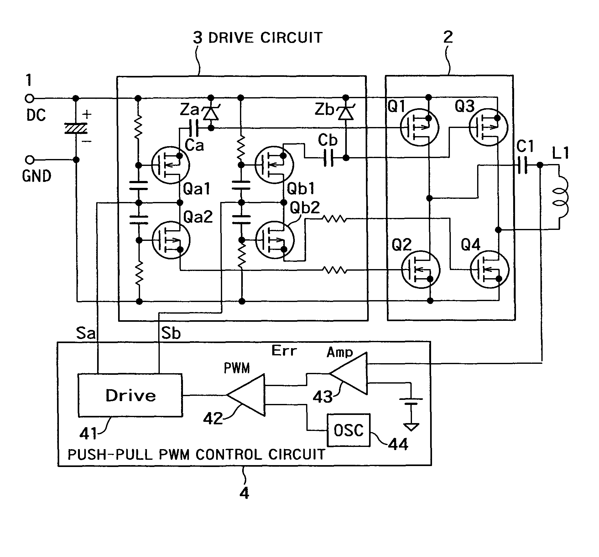
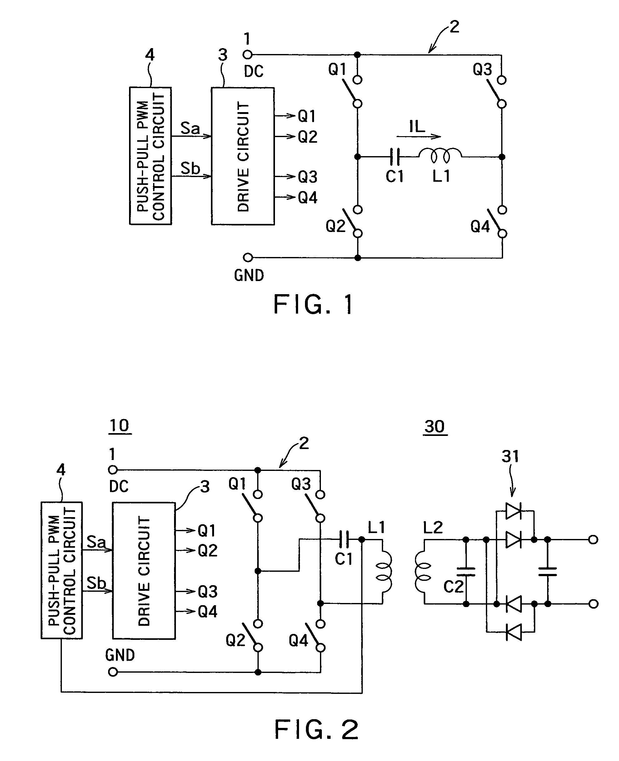
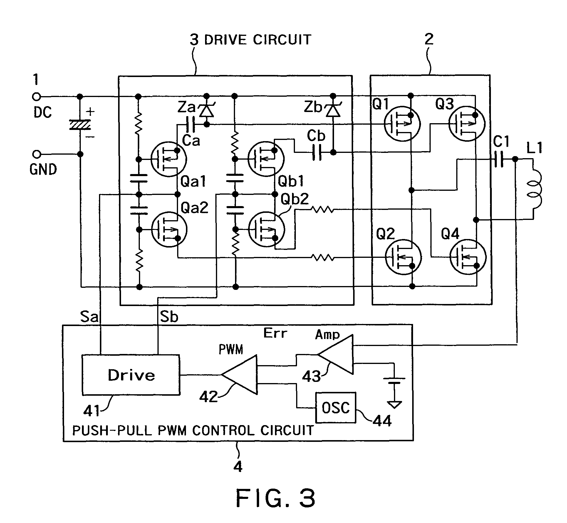
[0017]A non-contact electric power transmission circuit according to an embodiment of the invention includes an electric power transmission circuit and an electric power receiving circuit. The electric power transmission circuit includes a full bridge circuit and a resonant type full bridge circuit. A direct-current power supply is used as an input of the full bridge circuit, the full bridge circuit includes two sets of switching elements, two switching elements being connected in series in each set of the switching elements, a drive circuit alternately feeds a pulse signal to gates of the switching elements to perform switching of the direct-current input in the full bridge circuit, and a serial resonant circuit of a resonant capacitor and an electric power transmission coil is connected to an output of the full bridge circuit in the resonant type full bridge circuit. The electric power receiving circuit includes an electric power receiving coil and a rectifying and smoothing circu...


PUM

PropertyMeasurementUnit
voltageaaaaaaaaaa
dead timeaaaaaaaaaa
floating capacitanceaaaaaaaaaa

Abstract

A non-contact electric power transmission circuit according to an embodiment of the invention includes an electric power transmission circuit and an electric power receiving circuit. The electric power transmission circuit includes a full bridge circuit and a resonant type full bridge circuit. A direct-current power supply is used as an input of the full bridge circuit, the full bridge circuit includes two sets of switching elements, two switching elements being connected in series in each set of the switching elements, a drive circuit alternately feeds a pulse signal to gates of the switching elements to perform switching of the direct-current input in the full bridge circuit, and a serial resonant circuit of a resonant capacitor and an electric power transmission coil is connected to an output of the full bridge circuit in the resonant type full bridge circuit. The electric power receiving circuit includes an electric power receiving coil and a rectifying and smoothing circuit. The electric power receiving coil is electromagnetically coupled to the electric power transmission coil, and the rectifying and smoothing circuit rectifies an output of the electric power receiving coil. In the non-contact electric power transmission circuit, a push-pull output PWM control circuit is provided in the drive circuit that controls the full bridge circuit, and only one of the switching elements in each set of switching elements performs a regenerative operation. Therefore, a non-contact electric power transmission circuit in which the resonant type full bridge circuit can be controlled by PWM control at a level similar to that of a phase shift operation can be provided.

Description

BACKGROUND OF THE INVENTION[0001]1. Field of the Invention[0002]The present invention relates to a non-contact electric power transmission circuit, particularly to a method for controlling an electric power transmission circuit.[0003]2. Description of the Related Art[0004]As to a conventional non-contact electric power transmission circuit, a resonant type full bridge circuit system is generally used as a high-efficiency non-contact electric power transmission circuit in a low DC input.[0005]However, in a drive circuit of a general PWM control system, a duty ratio is set equal to or lower than 50% to provide a dead time in order to prevent switching elements from being simultaneously turned on to pass a short-circuit current. A period during which all the switching elements are turned off is generated due to the dead time. At this point, a voltage waveform at both ends of the switching element vibrates largely during the turn-off period. This is because an excitation current vibrate...

Claims


Application Information

Patent Timeline
Patent Type & Authority Patents(United States)
IPC IPC(8): H01F38/00H02M3/28
CPCH02M7/53871Y02B70/1441Y02B70/10
Inventor KOJIMA, HIDEKI
Owner MURATA MFG CO LTD
Why Eureka
Try Eureka