Radiation patternable CVD film

a patternable, cvd technology, applied in the direction of photomechanical equipment, instruments, originals for photomechanical treatment, etc., can solve problems such as problematic thinning of photoresists, and achieve the effect of plasma-enhanced chemical vapor deposition

Inactive Publication Date: 2013-06-18
APPLIED MATERIALS INC
View PDF10 Cites 282 Cited by
  • Summary
  • Abstract
  • Description
  • Claims
  • Application Information

AI Technical Summary

Problems solved by technology

However, as pattern sizes shrink, thicker photoresists are problematic.
Such problems arise during development, where the surface tension the solution pulls on the lines of the pattern, which is known as pattern collapse.

Method used


Image

  • Radiation patternable CVD film
  • Radiation patternable CVD film
  • Radiation patternable CVD film

Examples


example 1

PECVD Deposition of Film Using Trisilylamine and Exposure to Radiation in Vacuum

[0074]A film was deposited using PECVD and trisilylamine as a precursor. The deposition conditions included a chamber pressure of 4 torr and a temperature of 100° C. The plasma had an RF power of 100 W. The TSA precursor was flowed at a rate of 200 sccm, while nitrogen and hydrogen were each flowed at a rate of 1000 sccm.

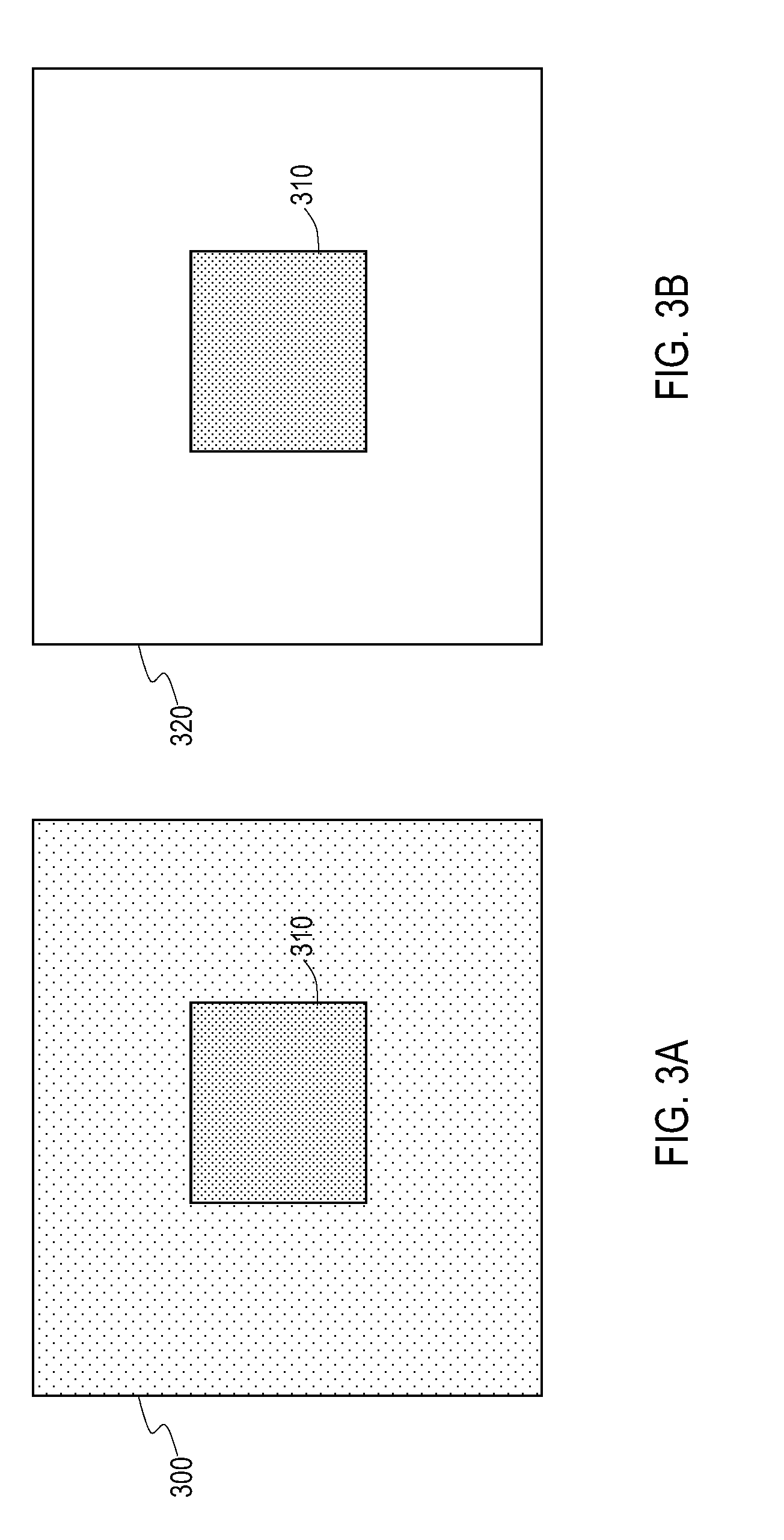
[0075]The deposited film was then exposed to an e-beam at 25 μC / cm2. Development consisted of puddle development for 60 seconds in a 0.26 normal TMAH solution in water.

[0076]The results showed that the film was sensitive to e-beam exposure carried out in a vacuum. The exposed film was also able to be developed using TMAH. FIGS. 3A and B are representations of optical microscope images taken of the film exposed to the e-beam before (FIG. 3A) and after (FIG. 3B) development. As seen in FIG. 3A, after exposure to the e-beam, a color change was observed in the portion of the film exposed 310...

example 2

PECVD Deposition of TSA and Exposure to Radiation in Presence of Oxygen

[0078]A film was deposited using plasma enhanced chemical vapor deposition. The film stack was comprised of 400 Angstroms of photoresist on 4000 Angstroms of APF. Film deposition was carried out at 4 torr of chamber pressure and at 100 C. The precursor was TSA, and was flowed at 200 sccm. The carrier plasma was a plasma containing argon flowed at 2000 sccm and had an RF value of 100 W. Plate spacing was 300 mil. The deposited film was then exposed to 25 mJ of 193 nm light. Development consisted of puddle development for 60 seconds in a 0.26 normal TMAH solution in water. After development, the film was etched using an oxygen-based plasma.

[0079]The deposited film demonstrated patterning using conventional photoresist processing equipment and chemicals. The film also demonstrated utility as a hard mask for etch transfer of features into the substrate.

[0080]FIG. 5 is FTIR spectra of film characterization of the depo...


PUM

PropertyMeasurementUnit
sizeaaaaaaaaaa
sizeaaaaaaaaaa
wavelengthaaaaaaaaaa

Abstract

Methods for forming photoresists sensitive to radiation on a substrate are provided. Described are chemical vapor deposition methods of forming films (e.g., silicon-containing films) as photoresists using a plasma which may be exposed to radiation to form a pattern. The deposition methods utilize precursors with cross-linkable moieties that will cross-link upon exposure to radiation. Radiation may be carried out in the with or without the presence of oxygen. Exposed or unexposed areas may then be developed in an aqueous base developer.

Description

BACKGROUND[0001]Embodiments of the present invention generally relate to radiation sensitive photoresist materials and methods of manufacturing and patterning such photoresists.[0002]In the manufacture of integrated circuits (IC) or chips, patterned exposure of light is used to define useful shapes or features on the surface of a substrate such a semiconductor wafer, typically in a photosensitive photoresist material. Feature sizes on chips are continually becoming smaller, requiring more sophisticated shorter wavelength lithography technologies. Next generation lithography (NGL) is expected to replace the current optical lithography method, for example, in the 20 nm technology node and beyond. Extreme ultraviolet (EUV) lithography (EUVL) EUVL shows promise as a next generation lithography technique, as well as electron beam (e-beam) lithography.[0003]Extreme ultraviolet lithography (“EUVL”) employs short wavelength radiation (“light”) in the approximate range of 10 nanometers (nm) ...

Claims


Application Information

Patent Timeline
Patent Type & Authority Patents(United States)
IPC IPC(8): G03C5/00G03F7/00G03F7/027G03F7/075G03F7/039
CPCG03F7/0752G03F7/094G03F7/16H01L21/31144H01L21/02219H01L21/02274H01L21/311H01L21/0217H01L21/0274H01L21/2053
Inventor WEIDMAN, TIMOTHY W.MICHAELSON, TIMOTHYDEATON, PAULINGLE, NITIN K.MALLICK, ABHIJIT BASUCHATTERJEE, AMIT
Owner APPLIED MATERIALS INC
Why Eureka
Try Eureka