Optical mode transformer, in particular for coupling an optical fiber and a high-index contrast waveguide

a transformer and optical fiber technology, applied in the field of optical mode transformers, can solve the problems of high coupling loss and high power loss of coupling, and achieve the effect of avoiding losses

Active Publication Date: 2013-07-09
GOOGLE LLC +1
View PDF20 Cites 35 Cited by
  • Summary
  • Abstract
  • Description
  • Claims
  • Application Information

AI Technical Summary

Benefits of technology

[0015]The present invention relates to an optical mode transformer to efficiently couple an optical fiber to a high index contrast waveguide (HC waveguide). In particular, mode transformer of the present invention makes possible an efficient coupling of an HC waveguide to a standard single-mode fiber (in the following, shortly, SM fiber). The meaning of “high index contrast” will be better clarified below.
[0016]A main goal of the invention is to provide a mode transformer that enables a low-loss coupling between the SM fiber mode and the HC waveguide mode, e.g., with an optical loss between fiber and the HC waveguide of not more than 2 dB per facet, preferably not more than 1 dB per facet.
[0017]This transformer can be used, for example, to efficiently couple an optical mode from a standard fiber, whose typical single-mode dimension of the modal area is approximately 80 μm2, to the mode in a HC planar waveguide, whose single modal area is typically equal or less than 1 μm2, and vice versa.

Problems solved by technology

One of the problems of the so called “Silicon Photonics” is the efficient coupling of high-contrast index waveguide, such as Si-waveguides, to the standard single mode optical fiber.
The difference in mode size prevents to directly connect the single mode fiber to the high-index contrast waveguide, for example through a butt coupling, because the coupling can give rise to a high power loss, due to the difference in the mode size, the latter being typically of at least an order of magnitude.
The difference in refractive index causes a mode velocity difference between the waveguide and the fiber, resulting again in a high coupling loss when a direct coupling is performed.

Method used


Image

  • Optical mode transformer, in particular for coupling an optical fiber and a high-index contrast waveguide
  • Optical mode transformer, in particular for coupling an optical fiber and a high-index contrast waveguide
  • Optical mode transformer, in particular for coupling an optical fiber and a high-index contrast waveguide

Examples


example 1

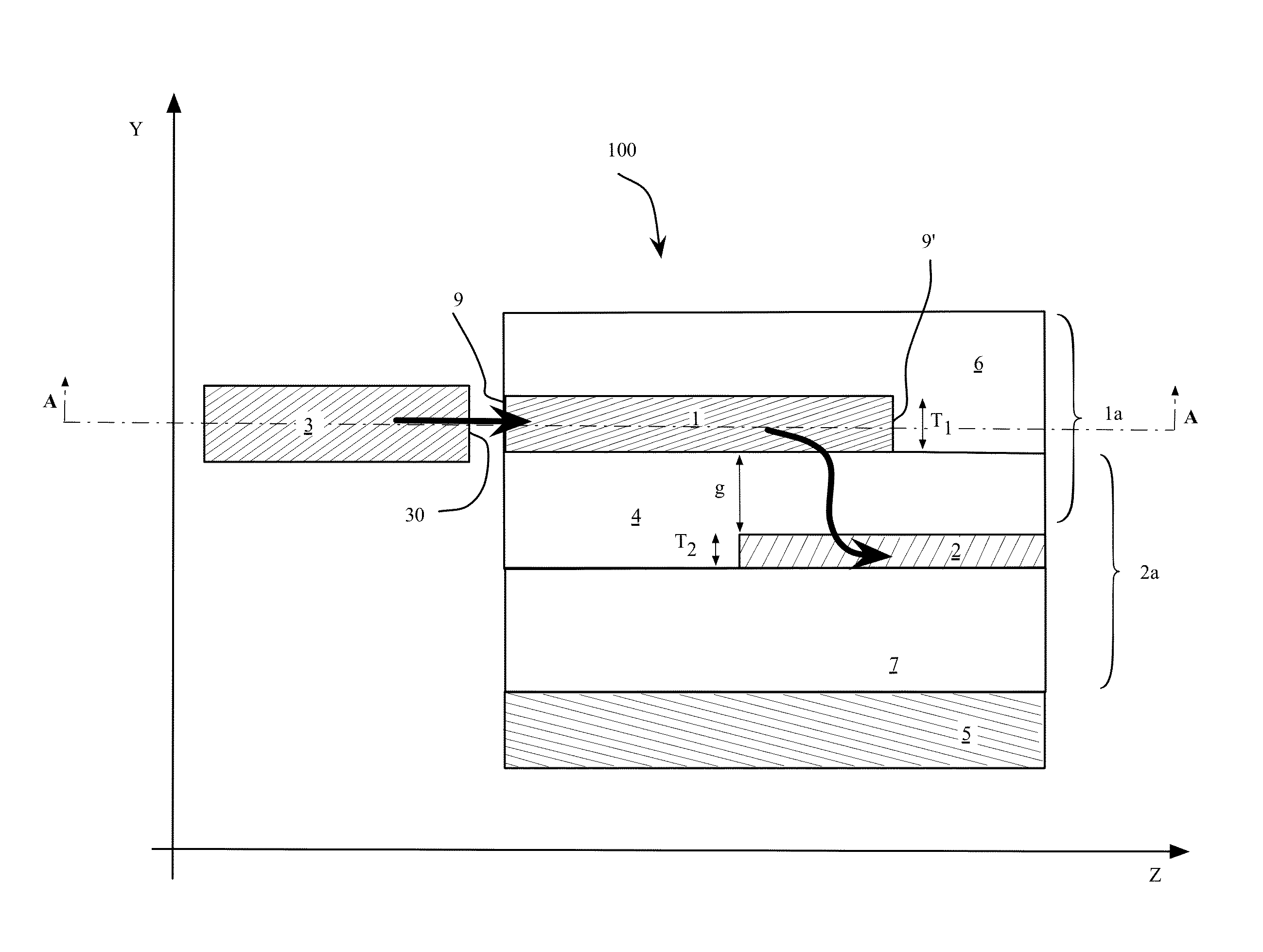
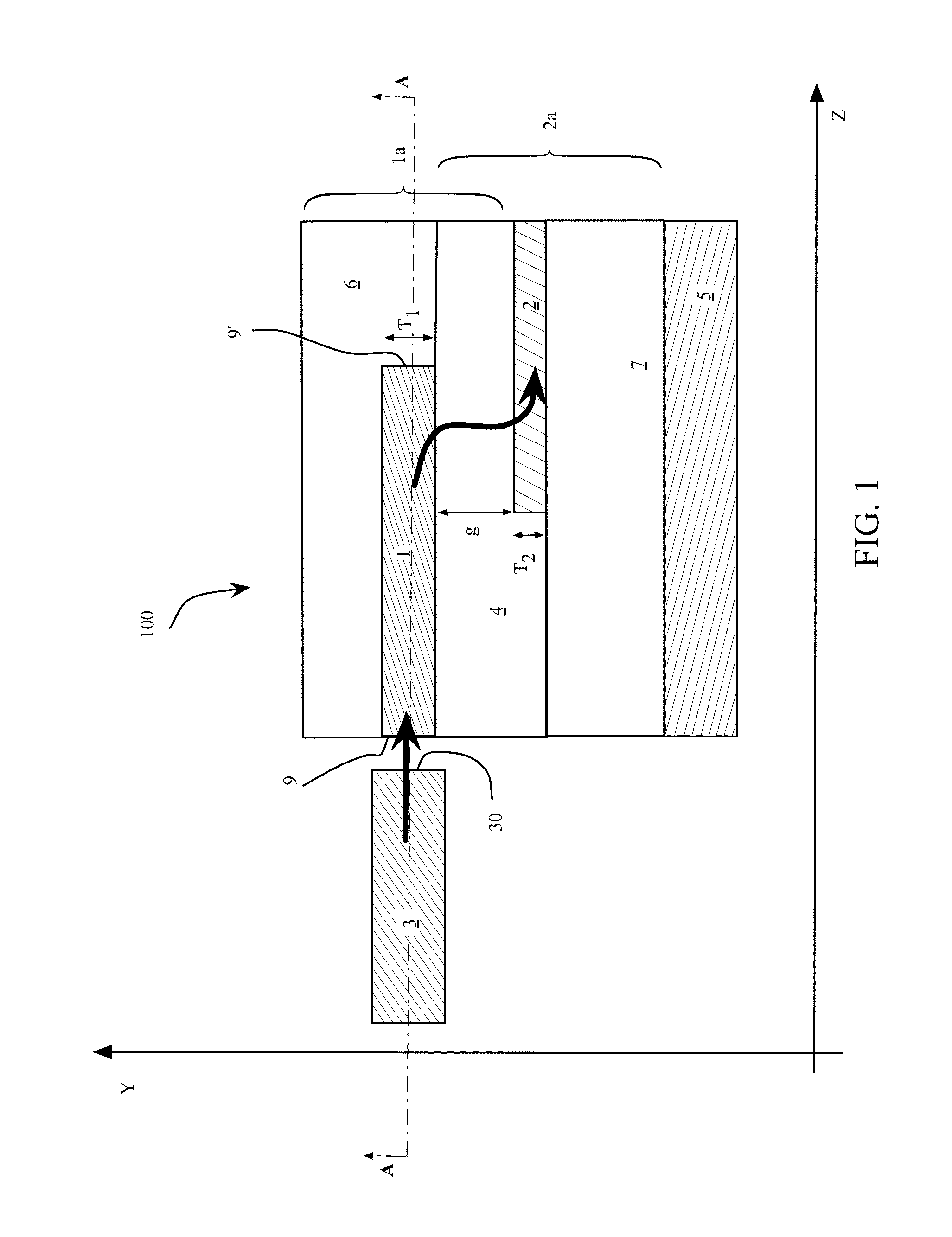
[0133]A SiO2:Ge first waveguide core, with nfirst core=1.483 and Δn1=2.5% having a square cross section of 2.6 μm×2.6 μm as guiding dimensions outside the coupling region is vertically arranged on top of a 150 nm thick Si waveguide (nsecond core=3.4756, Δn2=40%), the two being separated by a 1.2 μm an oxide layer (TEOS) having ncladding=1.446 at 1550 nm. First and second core are vertically aligned, i.e., no lateral misalignments exist between the first and the second waveguide. The thicknesses of both cores 1,2 remain substantially unchanged along the transformer 100 and therefore they are not further mentioned.

[0134]In this Example, the dimensions of the cores at the first cross section of FIG. 7a are W2IN=100 nm=the width of the taper tip realized in the Si waveguide, and W1IN=the thickness of the first core=2.6 μm. The first section of the overlapping region has a length L1 equal to 500 μm. At the second cross section of FIG. 7b, the second core 2 has an intermediate width W2MID...

example 2

[0138]A transformer identical to the transformer of Example 1, with the exception of the first core dimensions, has been realized by the Applicants.

[0139]In detail, referring back to FIGS. 7a and 7b, the dimensions of the cores of the transformer in this Example 2 are the following. The guiding portion of the first waveguide core 1 has a constant cross section of 3.6 μm×1.5 μm, leading therefore to an input width at the cross section represented in FIG. 7a of W1IN=3.6 μm for the first waveguide, while the width of the second waveguide core is, as in Example 1, W2IN=100 nm. The gap g between the two cores is still of 1.2 μm. At the end of the first section, having L1 equal to 500 μm, i.e., at the position depicted in the second cross section of FIG. 7b, the second core 2 has an intermediate width W2MIDDLE=200 nm, and the first core 1 is at its smallest width W1MIDDLE=1.2 m, which remains constant till the end of the overlapping region. At the output, i.e., at the end of the second se...

example 3

[0143]The same structure of Example 1 has been realized (same materials and waveguide dimensions), however first and second waveguide have 1 μm lateral misalignment. This embodiment is shown in the cross section FIG. 12, where the geometrical axes of the first and second waveguide core are schematically identified with a dot. The transformer according to this Example is globally indicated with 100′. A 1 μm lateral misalignment stands for a distance along the X direction between the two waveguides core axes of d=1 μm.

[0144]According to the performed numerical simulations, Applicants have observed that polarization mixing takes place to a minor extent in the transformer 100′ realized according to Example 3. The observed polarization coupling is limited to the amount of 20% and it is reversible, i.e., after a given propagating distance within the first waveguide, the polarization state of the travelling mode “returns” to the input polarization. At the output of the taper of the second ...


PUM


Abstract

An optical mode transformer comprises a first waveguide including a first core, a first cladding and an end facet configured to be coupled to an optical fiber. A second waveguide comprises a second core and a second cladding, and is arranged with respect to the first waveguide so as to realize an evanescent optical coupling with the first waveguide. The second core comprises a tapered region, in at least a portion of which the evanescent coupling takes place.The first core and the second core are separated by a gap. A first refractive index contrast of the first waveguide is less than a second refractive index contrast of the second waveguide.

Description

TECHNICAL FIELD[0001]The present invention relates to an optical mode transformer for efficiently coupling a single mode optical fiber to a high index contrast waveguide. In particular, the transformer of the invention is designed to minimize overall losses and to obtain low polarization depending losses and / or to minimize polarization mixing.TECHNOLOGICAL BACKGROUND[0002]The present invention relates to the field of semiconductor and dielectric optical components and devices used for optical transmission or optical digital data processing, in particular to the field of optical mode transformers between two waveguides.[0003]One of the problems of the so called “Silicon Photonics” is the efficient coupling of high-contrast index waveguide, such as Si-waveguides, to the standard single mode optical fiber. Typically, a standard single-mode fiber has a mode field diameter comprised between 8 and 12 μm, more typically of 9-10 μm. The reason of the aforementioned problem lies in the diffe...

Claims


Application Information

Patent Timeline
Patent Type & Authority Patents(United States)
IPC IPC(8): G02B6/26G02B6/42G02B6/10
CPCG02B6/1228G02B6/305
Inventor SOCCI, LUCIANOBOLLA, LORENZOGALLI, PAOLAROMAGNOLI, MARCOGHIDINI, SILVIA
Owner GOOGLE LLC
Why Eureka
Try Eureka