Method and apparatus for using multiple laser beams to weld members that are separated by a gap

a technology of laser beams and gap welding, which is applied in the direction of laser beam welding apparatus, welding apparatus, manufacturing tools, etc., can solve the problems of inability to completely eliminate spattering, short circuit, and disadvantages of conventional hybrid laser processing methods, and achieves low thermal effect, high speed, and eliminate the entrance of spatter

Active Publication Date: 2013-07-16
PANASONIC CORP
View PDF16 Cites 2 Cited by
  • Summary
  • Abstract
  • Description
  • Claims
  • Application Information

AI Technical Summary

Benefits of technology

[0019]In view of the above-described disadvantages, the present invention has an object to provide a fusion welding method that eliminates the entrance of spatters and welding defects such as cracks or porosities even with a gap in a part to be welded, and also has a low thermal effect on the periphery and performs fusion welding at high speed.
[0025]As described above, according to the present invention, when the hybrid laser beam is used to fill the gap in the part to be welded with molten metal from both sides thereof, the first member and the second member can be welded by, for example, brazing even if there is a gap in the part to be welded between the butted first member and second member. Further, keyholes are formed in the first member and the second member with a predetermined penetration width, thereby completely preventing spatters from entering through the gap.
[0026]According to the present invention, when the hybrid laser beam is used to fill the gap in the part to be welded in the lower portion of a molten pool formed in the first member, the first member and the second member can be welded by, for example, brazing even if there is a gap in the part to be welded between the lapped first member and second member. Further, the first member and the second member are welded in the lower portion of the molten pool formed in the first member, thereby completely preventing the entrance of spatters.
[0027]Further, the low-intensity laser beam gradually cools a welded part, thereby completely preventing welding defects such as cracks or porosities. Meanwhile, the first high-intensity laser beam and the second high-intensity laser beam melt the application portion instantaneously, thereby reducing thermal effects on the periphery to allow for fusion welding at high speed.

Problems solved by technology

However, the conventional hybrid laser processing method has disadvantages described below.
The conventional hybrid laser processing method is a kind of fusion welding which can reduce spattering but cannot completely eliminate spattering.
If spatters enter, they may cause a short circuit and ignite the lithium-ion battery.
Thus, the lithium-ion battery has a higher energy density and contains a flammable substance, and can easily overheat and be ignited suddenly in a short circuit.
In particular, if a large lithium-ion battery (hereinafter referred to as an on-vehicle storage battery) to be mounted in a hybrid car or an electric vehicle is ignited, the on-vehicle storage battery burns, and further the car itself burns and causes a serious accident.
However, unfortunately, in a lithium-ion battery, gaps are easily created in welded portions because of the following points (1) to (4).
Thus, an aluminum can is warped more significantly than an iron can and easily creates a large gap.
A battery with such a size exhibits large variations in warp or mating, inevitably creating a gap in a part to be welded.
However, in the conventional hybrid laser processing method, it is difficult to completely eliminate the gap.
Thus, in the conventional hybrid laser processing method, it is difficult to prevent spattering when welding the aluminum can and a sealing plate.
Thus, heat is more easily lost to the periphery of a part to be welded in an aluminum can than in an iron can.
If the part to be welded is penetrated, the interior is damaged.
Thus, when the melting point is reached, melting rapidly progresses, thereby making it difficult to control the penetration depth of the part to be welded.
Further, since aluminum is easily oxidized, aluminum having melted and oxidized cannot be welded.
However, although spattering does not occur, the cost of brazing and soldering is high.
Further, unfortunately, there is no aluminum brazing filler metal that satisfies a useful life of 15 years of an on-vehicle storage battery.

Method used


Image

  • Method and apparatus for using multiple laser beams to weld members that are separated by a gap
  • Method and apparatus for using multiple laser beams to weld members that are separated by a gap
  • Method and apparatus for using multiple laser beams to weld members that are separated by a gap

Examples


first embodiment

(First Embodiment)

[0058]Now, a first embodiment according to the present invention will be described.

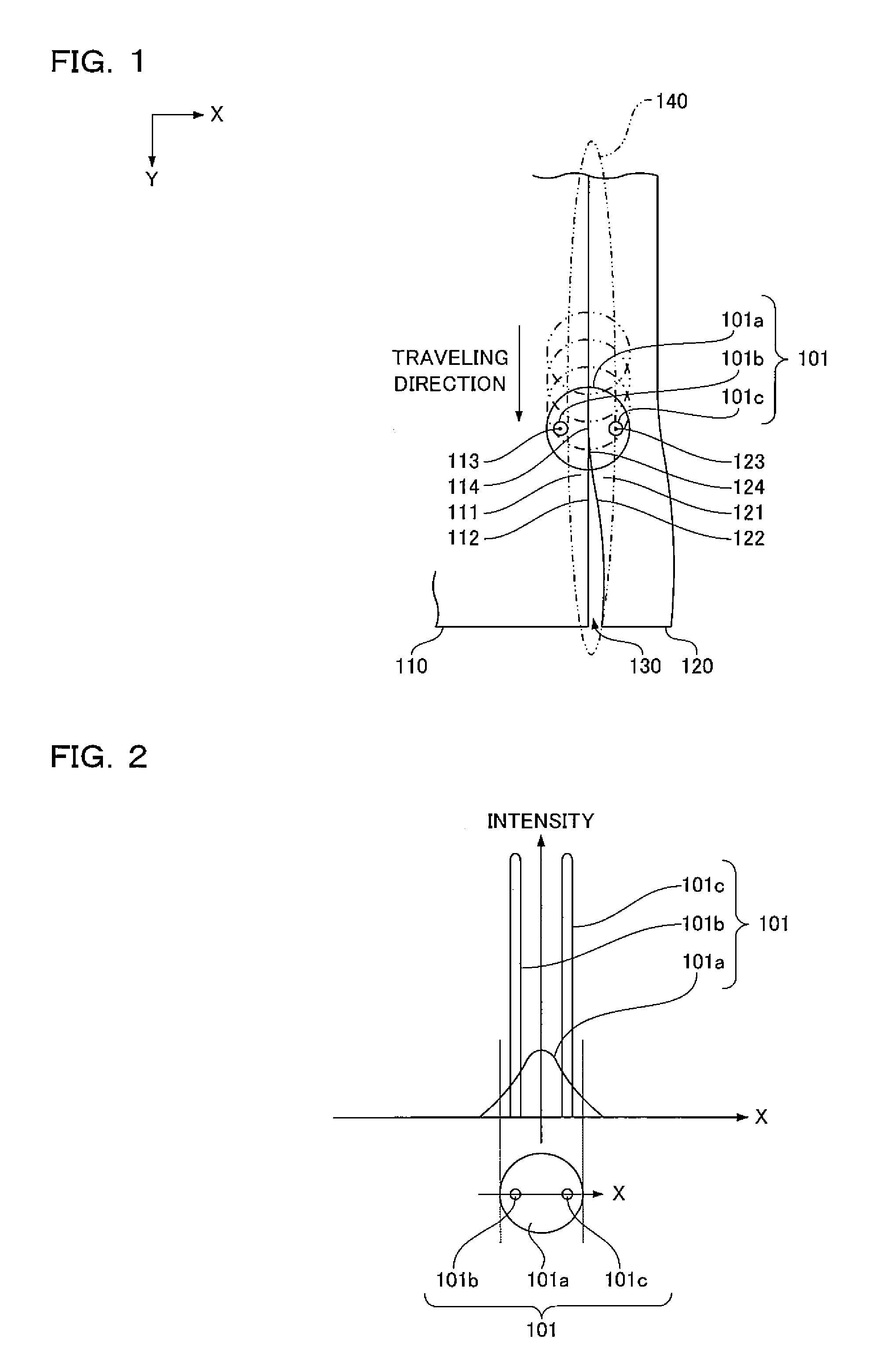
[0059]First, in a fusion welding method of this embodiment, as shown in FIG. 1, a hybrid laser beam 101 of FIG. 2 is used to butt-join a first member 110 and a second member 120. At this time, the hybrid laser beam 101 is applied to a gap 130 between the first member 110 and the second member 120 and to a periphery 140 of the gap while being moved along the gap 130 between the first member 110 and the second member 120 to fill the gap 130 with molten metal from both sides of the gap.

[0060]In the drawings, X and Y directions are horizontal and Z direction is vertical.

101>

[0061]The hybrid laser beam 101 is obtained by mixing, on a low-intensity laser beam 101a, a first high-intensity laser beam 101b and a second high-intensity laser beam 101c. The low-intensity laser beam 101a has intensity distribution such as Gaussian distribution. The first high-intensity laser beam 101b and the sec...

example 1

FUSION WELDING EXAMPLE 1

First Butt-Welding Example

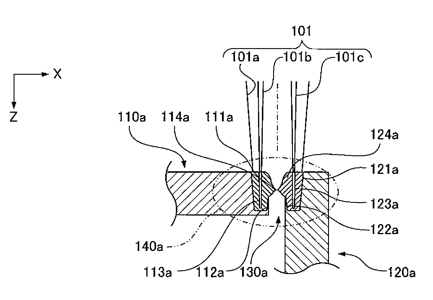
[0102]In the following description, the hybrid laser beam 101 is applied directly from above to butt-weld a first member 110a and a second member 120a. The drawings show a state as viewed from the traveling direction of the hybrid laser beam 101. In the drawings, the position of the optical axis of the low-intensity laser beam 101a is indicated by a dashed line.

[0103]As an example, as shown in FIGS. 7A to 7C, the first member 110a and the second member 120a are herein metal plates. The first member 110a is placed so as to extend in the X direction. The second member 120a is placed so as to extend in the Z direction. The side surface of the right end of the first member 110a is butted against the side surface of the upper end of the second member 120a. The upper surface of the right end of the first member 110a is flush with the upper surface of the upper end of the second member 120a. A gap 130a extends along the Y direction between ...

example 2

FUSION WELDING EXAMPLE 2

Second Butt-Welding Example

[0118]Next, in the following description, the hybrid laser beam 101 is applied directly from the side to butt-weld a first member 110b and a second member 120b. The drawings show a state as viewed from the traveling direction of the hybrid laser beam 101. In the drawings, the position of the optical axis of the low-intensity laser beam 101a is indicated by a dashed line.

[0119]As an example, as shown in FIGS. 9A to 9C, the first member 110b and the second member 120b are herein metal plates. The first member 110b is placed so as to extend in the X direction. The second member 120b is placed so as to extend in the Z direction. The lower surface of the right end of the first member 110b is butted against the upper surface of the upper end of the second member 120b. The side surface of the right end of the first member 110b is flush with the side surface of the upper end of the second member 120b. A gap 130b extends along the Y directio...


PUM

PropertyMeasurementUnit
widthaaaaaaaaaa
wavelengthaaaaaaaaaa

Abstract

A fusion welding method includes the steps of: generating a hybrid laser beam obtained by mixing a low-intensity laser beam with a first high-intensity laser beam and a second high-intensity laser beam; moving the hybrid laser beam along a gap between a first member and a second member; and melting the first member and the second member in the periphery of the gap with the hybrid laser beam, and filling the gap with the melt of the first member and the melt of the second member to weld the first member and the second member, wherein the first high-intensity laser beam is applied to the area of the first member to which the low-intensity laser beam is applied, and the second high-intensity laser beam is applied to the area of the second member to which the low-intensity laser beam is applied.

Description

FIELD OF THE INVENTION[0001]The present invention relates to a fusion welding method in which a gap in a part to be welded between a first member and a second member is filled with melt obtained by melting the part to weld the first member and the second member.BACKGROUND OF THE INVENTION[0002]Conventionally, various techniques for laser processing have been proposed. One of the techniques is a method of processing a workpiece using a hybrid laser beam obtained by mixing two laser beams (hereinafter referred to as a hybrid laser processing method) (for example, see Japanese Patent Laid-Open No. 2005-254328).[0003]For example, as shown in FIG. 29, in the hybrid laser processing method, a hybrid laser beam 1 obtained by mixing a first laser beam 1a and a second laser beam 1b is applied to a workpiece 10. The first laser beam 1a is a pulse laser beam having a wavelength different from that of the second laser beam 1b. The second laser beam 1b is a CW (Continuous Wave) laser beam having...

Claims


Application Information

Patent Timeline
Patent Type & Authority Patents(United States)
IPC IPC(8): B23K26/20B23K26/14B23K26/00B23K26/21
CPCB23K26/0617B23K1/0056
Inventor SAKURAI, TUTOMUKUMAZAWA, SEIJIKATAOKA, HIDENAO
Owner PANASONIC CORP
Why Eureka
Try Eureka