X-rays source comprising at least one electron source combined with a photoelectric control device

a control device and electron source technology, applied in the field of radiation sources, can solve the problems of affecting the quality of the received image, difficult in particular to discriminate between substances having similar densities, and limited detection and identification capability, and achieve the effect of high precision and very sensitive control

Active Publication Date: 2013-08-06
THALES SA
View PDF37 Cites 16 Cited by
  • Summary
  • Abstract
  • Description
  • Claims
  • Application Information

AI Technical Summary

Benefits of technology

[0032]Advantageously, the cold source may thus be at the high negative voltage and the target anode may be electrically grounded, simplifying the way in which the target anode is cooled.
[0081]the applied illumination serves for individually controlling the current of each emitter, thus avoiding the risks of destroying these emitters due to differences in height of the nanotubes, which risks are encountered when control takes place via an electrode or flat conductor, the voltage of which is varied; and

Problems solved by technology

However, detection and identification capability remains limited.
It is difficult in particular to discriminate between substances having similar densities.
In the case of directly-heated thermionic cathodes (FIG. 1A) having a filament Fil facing an anode A, or indirectly-heated thermionic cathodes (FIG. 1B) having a filament Fil heating an impregnated cathode Cath facing an anode A, a first limitation stems from the thermal inertia of such cathodes, preventing rapid modulation of the current and therefore of the X-ray dose rate (for a given energy, the dose rate is often controlled by the current output by the cathode; if the current rise or current fall is not steep, there will be transient X-radiation emission phases that may impair the quality of the received image on the detector).
A second limitation stems from the need to have a complex power supply for the filament, if this is a high-voltage supply.
The various insulating passages for biasing the grid, filament and cathode are also more complex and bulkier as they have to withstand the high voltages (20 to 600 kV) generally encountered in radiation-generating tubes.
Given these electrical connection and insulation constraints, it is very difficult to envisage two (or more) X-ray sources within the same vacuum envelope.
However, this diode-type arrangement does not make it possible for the intensity of the emitted current to be controlled independently of the anode voltage.
For a cold cathode, notably a carbon nanotube cathode, associated with a grid, there are however several limitations due to the presence of the grid in the field of application of radiation-generating tubes.
Among these limitations, the following may be noted:the cathode-grid capacitance limits the maximum modulation frequency;the current emitted by the cathode varies exponentially with the voltage applied to the grid, degrading the quality with which the current emitted by the cathode is controlled;since the grid is not entirely transparent to the electron stream, it intercepts 30 to 50% of the current emitted by the cathode, promoting dimensional variations in this grid caused by it being heated, and consequently generating instability in the current emitted by the cathode because of the exponential variation mentioned above, while thermal inertia and embrittlement are aggravating factors;the fraction of current intercepted by the grid and the grid heating resulting therefrom are also limitations for using this type of cathode with high currents (a few tens of mA).
These systems are generally unwieldy and complicated, and they require lengthy analysis times incompatible with the latest needs.

Method used


Image

  • X-rays source comprising at least one electron source combined with a photoelectric control device
  • X-rays source comprising at least one electron source combined with a photoelectric control device
  • X-rays source comprising at least one electron source combined with a photoelectric control device

Examples


first exemplary embodiment

[0099]According to a first embodiment of the invention, illustrated in FIG. 5, the radiation source is a mono-beam source and comprises a vacuum chamber 20, high-voltage power supply means 21 and electrical insulation means 22, an illumination source 23 directing a light beam 24 onto an optically reflective device 25, i.e. reflective for the wavelengths used, so as to excite the photosensitive layers of a cathode 26 for generating an electron stream 27 sent to a target 28. The bombardment of said target then generates the stream of X-rays 30 through a window 29 transparent to said X-rays with which the chamber is equipped. Advantageously, the chamber may also be equipped with means 31 for cooling the target, which is intensely heated during bombardment by the electron streams.

second exemplary embodiment

[0100]The radiation source generates a multiplicity of X-ray streams 40i thanks to the presence of a series of chambers (X-ray tubes) 411 distributed in a circular support 42, said circular support also including means for distributing the power from a high-voltage power supply 43, as illustrated in FIGS. 6A and 6B.

third exemplary embodiment

[0101]The radiation source may also be a multi-beam source and may comprise a single chamber as illustrated in FIGS. 7A, 7B, 7C and 7D. According to the example shown, said chamber 50 may advantageously be of several forms incorporating variously arranged electron sources. The nonexhaustive examples show: a planar convergent organization (FIG. 7A); a circularly arranged parallel-beam organization (FIG. 7B); a perpendicularly arranged parallel-beam organization (FIG. 7C); and a matrix-arranged parallel-beam organization (FIG. 7D).

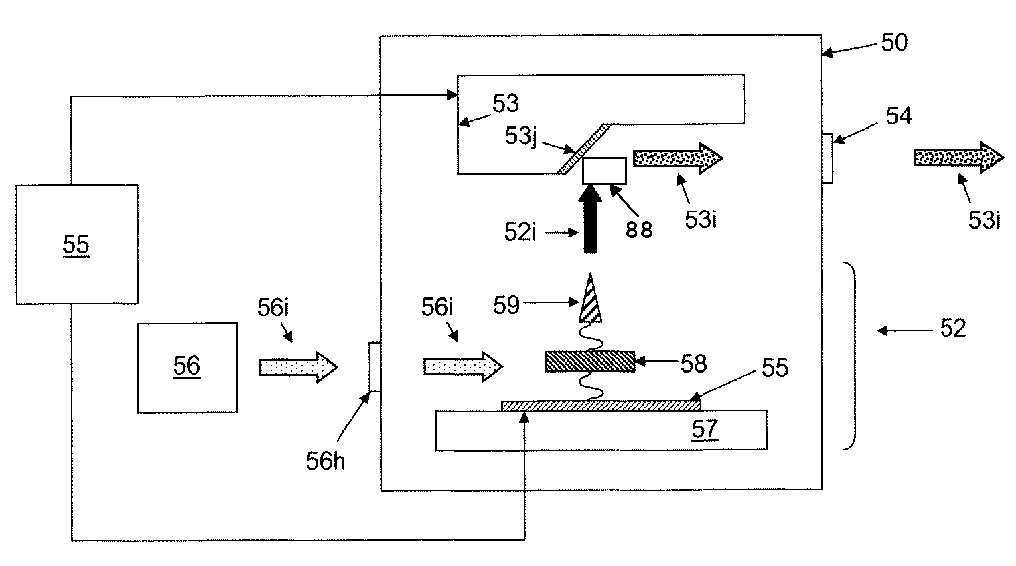
[0102]FIG. 8 illustrates an example of means for modulating 66 the electron spot on the target, associated only with the illumination zone (with neither a grid nor an emitter array mechanically determining the emission zones).

[0103]In general, the present invention provides, in response, a radiation source comprising a cold electron source subjected to an electric field and operating by field emission, and a photoconductive element placed in series with the ...


PUM


Abstract

A radiation source includes a vacuum chamber, means for injecting an optical wave, a cold source for emitting electrons, a power supply, an anode for emitting X-rays, and at least one window through which the X-rays exit. A light source delivers the optical wave, and the cold source includes at least one substrate with a conducting surface and is subjected to an electric field. The cold further includes a photoconductive element in which the current is controlled approximately linearly by the illumination and at least one electron-emitting element, the photoconductive element electrically connected in series between an emitting element and a conducting surface. Current photogenerated in the photoconductive device is equal to that emitted by the emitter or the group of emitters with which it is associated, and the emitted stream of X-rays is approximately linearly dependent on the illumination.

Description

CROSS-REFERENCE TO RELATED APPLICATIONS[0001]This application is a National Stage of International patent application PCT / EP2009 / 050809, filed on Jan. 23, 2009, which claims priority to foreign French patent application No. FR 08 00397, filed on Jan. 25, 2008, the disclosures of which are incorporated by reference in their entirety.FIELD OF THE INVENTION[0002]The field of the invention is that of radiation sources, generally used in industrial, scientific and medical applications so as to deliver a photon flux, notably for producing images using various reconstruction techniques in two or three spatial dimensions. These radiation sources are also useful in the security field, notably for inspecting baggage and parcels by X-rays.BACKGROUND OF THE INVENTION[0003]For a long time, fixed systems based on transmission X-ray imaging have been used for airport security. Over the last ten years or so, the requirements for security in public places have been growing and require systems on mob...

Claims


Application Information

Patent Timeline
Patent Type & Authority Patents(United States)
IPC IPC(8): H01J35/06
CPCH01J35/065H01J2235/068H01J2235/062
Inventor LEGAGNEUX, PIERREHUDANSKI, LUDOVICPONARD, PASCALBOURAT, CHRISTOPHESCHNELL, JEAN-PHILIPPE
Owner THALES SA
Why Eureka
Try Eureka