
Chip package including multiple sections for reducing chip package interaction

a chip package and interaction technology, applied in the field of integrated circuits, can solve the problems of increasing production yield, signal propagation delay no longer limited, and conductivity reduction of lines, so as to reduce the degree of deformation of the package substrate, reduce thermal expansion, and reduce the effect of interaction with the semiconductor di

Active Publication Date: 2013-08-13
TAIWAN SEMICON MFG CO LTD
View PDF5 Cites 3 Cited by
  • Summary
  • Abstract
  • Description
  • Claims
  • Application Information

AI Technical Summary

Benefits of technology

This approach significantly reduces mechanical stress and defects in the metallization system, improving production yield and reliability by allowing independent deformation of substrate sections and reducing thermal-induced stress on the semiconductor die.

Problems solved by technology

Thus, economic constraints drive semiconductor manufacturers to steadily increase the substrate dimensions, thereby also increasing the area available for producing actual semiconductor devices and thus increasing production yield.
For extremely scaled integrated circuits, the signal propagation delay is no longer limited by the circuit elements, such as field effect transistors and the like, but is limited, owing to the increased density of circuit elements requiring an even more increased number of electrical connections, by the close proximity of the metal lines, since the line-to-line capacitance is increased and the conductivity of the lines is reduced due to a reduced cross-sectional area.
However, the density and mechanical stability or strength of the low-k materials may be significantly less compared to the well-approved dielectrics silicon dioxide and silicon nitride.
In addition to the problems of reduced mechanical stabilities of advanced dielectric materials having a dielectric constant of 3.0 and significantly less, device reliability may also be affected by these materials during operation of sophisticated semiconductor devices due to an interaction between a chip and the package, wherein this interaction is caused by a thermal mismatch of the corresponding thermal expansion of the different materials.
The thermally or mechanically induced stress may, however, also act on the lower lying metallization layers, which may typically include low-k dielectrics or even ultra low-k (ULK) dielectric materials, thereby significantly increasing the probability of creating defects by delamination of these sensitive materials due to reduced mechanical stability and adhesion to other materials.
Moreover, during operation of the composite semiconductor device, i.e., the semiconductor chip attached to the corresponding package substrate, significant mechanical stress may also occur due to a significant mismatch in the thermal expansion behavior of the silicon-based semiconductor chip and the package substrate, since, in volume production of sophisticated integrated circuits, economic constraints typically require the usage of specified substrate materials for the package, such as organic materials, which may typically exhibit a different thermal conductivity and a different coefficient of thermal expansion compared to the silicon chip.
Consequently, a premature failure of the metallization system may occur.
As previously discussed, the ongoing shrinkage of critical dimensions of circuit elements has resulted in critical dimensions of transistors on the order of magnitude of 50 nm and significantly less in presently available sophisticated semiconductor devices that are produced by volume production techniques.
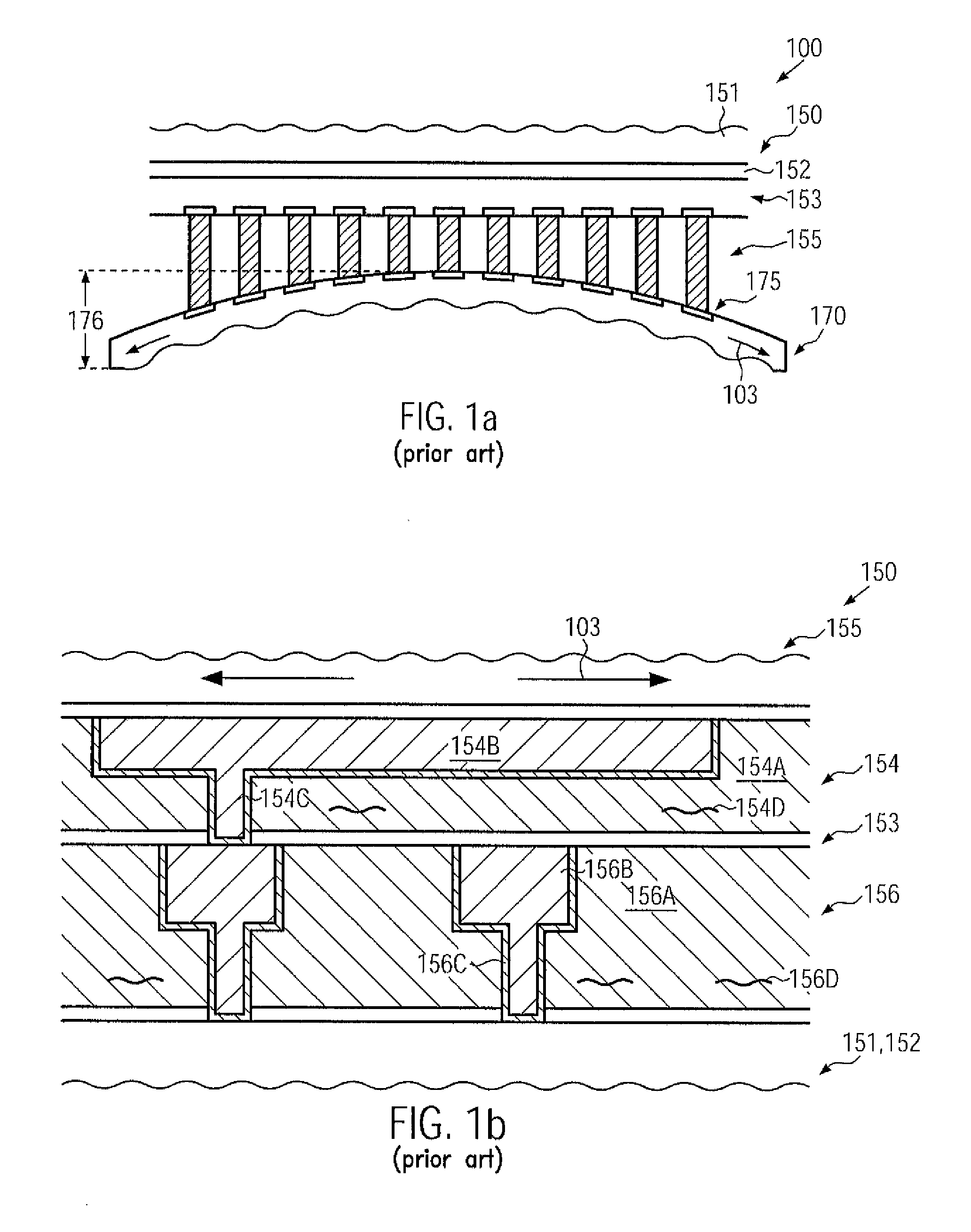
Due to the reduced mechanical stability and the reduced adhesion of sophisticated dielectric materials, corresponding defects typically occur, which thus affect the overall reliability and also production yield when operating or manufacturing the integrated circuit 100.
Consequently, the resulting delamination may finally result in a premature failure of the metallization system 153 or in an initial failure of the metallization system, thereby contributing to reduced production yield and reduced overall reliability of the integrated circuit 100 (FIG. 1a).
On the other hand, the increased complexity of the overall circuit layout may also require an increased number of stacked metallization layers, as previously explained, which may additionally result in a reduced overall mechanical stability of the metallization system.
In still other conventional approaches, less sophisticated dielectric materials are used in order to enhance the overall mechanical stability, thereby, however, sacrificing performance of the integrated circuits.

Method used


Image

  • Chip package including multiple sections for reducing chip package interaction
  • Chip package including multiple sections for reducing chip package interaction
  • Chip package including multiple sections for reducing chip package interaction

Examples


Embodiment Construction

[0033]Various illustrative embodiments of the invention are described below. In the interest of clarity, not all features of an actual implementation are described in this specification. It will of course be appreciated that in the development of any such actual embodiment, numerous implementation-specific decisions must be made to achieve the developers' specific goals, such as compliance with system-related and business-related constraints, which will vary from one implementation to another. Moreover, it will be appreciated that such a development effort might be complex and time-consuming, but would nevertheless be a routine undertaking for those of ordinary skill in the art having the benefit of this disclosure.

[0034]The present subject matter will now be described with reference to the attached figures. Various structures, systems and devices are schematically depicted in the drawings for purposes of explanation only and so as to not obscure the present disclosure with details ...


PUM


Abstract

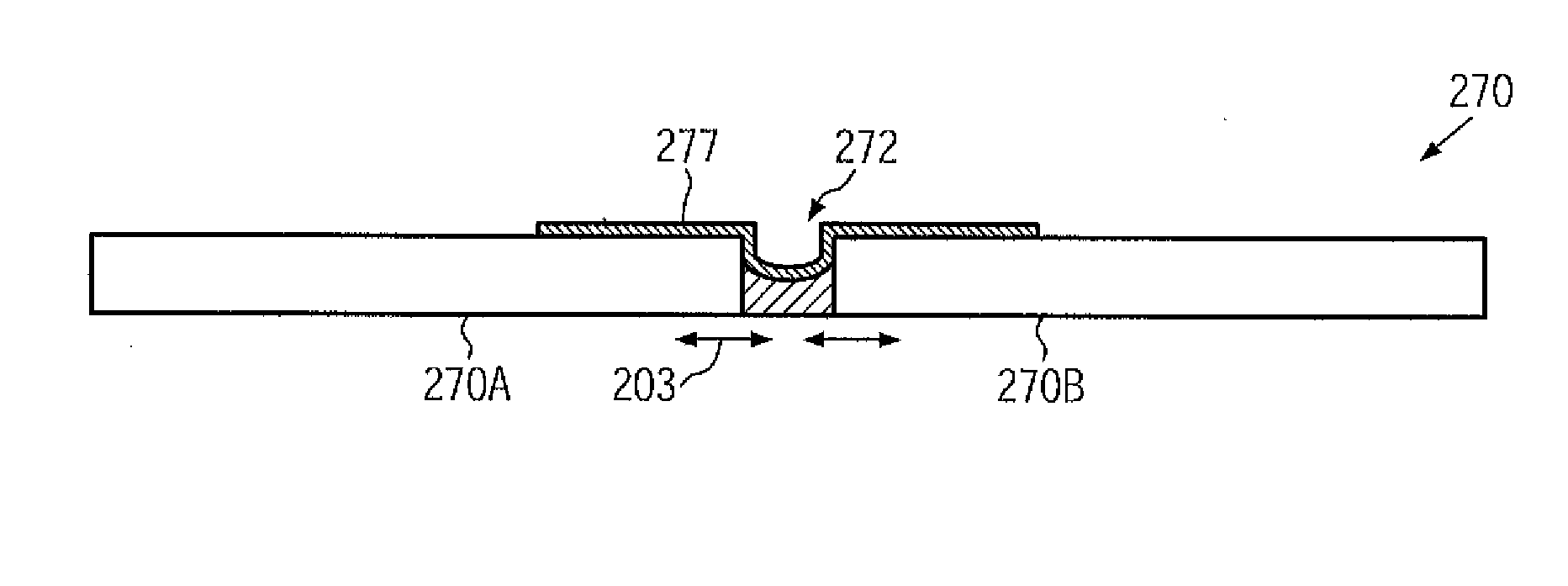
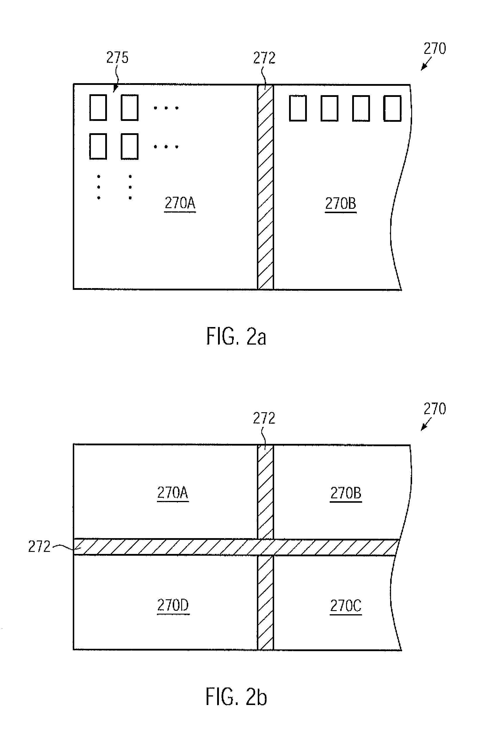
Thermally induced stress in a semiconductor die, i.e., in a complex metallization system thereof, may be reduced by “dividing” a package substrate into two or more substrate sections, which may have formed therebetween an appropriate stress buffer region, for instance a region of superior resiliency. In this case, the total deformation of the package substrate may be reduced, thereby also reducing the thermally induced stress forces in the complex metallization system of the semiconductor die. Hence, for a given size and complexity of a metallization system, an increased production yield and superior reliability may be achieved.

Description

BACKGROUND OF THE INVENTION[0001]1. Field of the Invention[0002]Generally, the present disclosure relates to integrated circuits, and, more particularly, to the techniques for reducing chip-package interactions caused by thermal mismatch between the chip and the package substrate.[0003]2. Description of the Related Art[0004]Semiconductor devices are typically formed on substantially disc-shaped substrates made of any appropriate material. The majority of semiconductor devices including highly complex electronic circuits are currently, and in the foreseeable future will be, manufactured on the basis of silicon, thereby rendering silicon substrates and silicon-containing substrates, such as silicon-on-insulator (SOI) substrates, viable base materials for forming semiconductor devices, such as microprocessors, SRAMs, ASICs (application specific ICs), systems on chip (SoC) and the like. The individual integrated circuits are arranged in an array on the wafer, wherein most of the manufac...

Claims


Application Information

Patent Timeline
Patent Type & Authority Patents(United States)
IPC IPC(8): H01L29/40
CPCH01L24/81H01L23/13H01L23/4985H01L2924/1306H01L2924/10253H01L2924/0001H01L2924/014H01L2924/01033H01L2924/01019H01L2924/01005H01L24/17H01L2224/1703H01L2224/81815H01L2924/01029H01L2924/01082H01L2924/3511H01L2224/131H01L2224/13099H01L2924/00H01L2924/14
Inventor CHUMAKOV, DMYTRO
Owner TAIWAN SEMICON MFG CO LTD
Learn More