Turbocharger

a turbocharger and turbocharger technology, applied in wind motors with perpendicular air flow, waterborne vessels, machines/engines, etc., can solve the problems of engine and air flow mass through the compressor slowing down, turbocharger continuing to spin, engine power loss, etc., to increase the flow of air into the engine, the effect of improving the torque/power output density of the engin

Active Publication Date: 2013-08-27
FORD GLOBAL TECH LLC +1
View PDF10 Cites 46 Cited by
  • Summary
  • Abstract
  • Description
  • Claims
  • Application Information

AI Technical Summary

Benefits of technology

[0003]Engines may use a turbocharger to improve engine torque / power output density. In one example, a turbocharger may include a compressor and a turbine connected by a drive shaft, where the turbine is coupled to the exhaust manifold side and the compressor is coupled to the intake manifold side. In this way, the exhaust-driven turbine supplies energy to the compressor to increase the flow of air into the engine.
[0005]A second source of surge may be caused in part by high levels of cooled exhaust gas recirculation (EGR). EGR may be used for reducing NOx emissions from diesel engines and for controlling knock in gasoline engines. High levels of EGR may increase compressor pressure while decreasing mass flow through the compressor causing the compressor to operate inefficiently or in the surge region.
[0007]Therefore, it can be desirable to increase the operating range of the compressor and the turbocharger by reducing the air flow rate before surge occurs and increasing the air flow rate before choke occurs. One solution that has been used to widen the operating point is a passive casing treatment. The passive casing treatment includes a pair of immovable slots that modify the air flow through the compressor. During low air mass flow conditions, the slots of the passive casing treatment may provide a path to recirculate partially pressurized air back to the compressor inlet. The recirculated air flowing through the compressor may enable less air to flow through the compressor before surge occurs. During high air mass flow conditions, the slots of the passive casing treatment may provide a path to short-circuit air flow through the compressor so that the choke occurs at a higher air mass flow rate.
[0009]As such, an example of a turbocharger to address the above issues is described. The turbocharger includes an active casing treatment, an impeller, a casing, and a diffuser. The impeller includes a full blade having a leading edge, a splitter having a leading edge, and an axis of rotation. The casing includes a compressor inlet, an intake passage, a recirculation passage, a recirculation port, a bleed port, and an injection port. The intake passage contains the impeller in a gas flow path downstream from the compressor inlet and upstream from the diffuser. The leading edge of the full blade is upstream of the leading edge of the splitter. The bleed port is downstream of the leading edge of the full blade and upstream of the leading edge of the splitter. The injection port is downstream of the leading edge of the splitter. The recirculation port is downstream of the compressor inlet, upstream of the impeller, and configured to enable gas to flow between the recirculation passage and the intake passage. The active casing treatment is configured to selectively control gas flowing through the bleed port, between the intake passage and the recirculation passage, and selectively control gas flowing through the injection port, between the intake passage and the recirculation passage. In this way, a port may be optimized for both choke and surge conditions and the operating range of the turbocharger may be extended.

Problems solved by technology

The reversal of air flow may cause the engine to lose power.
During tip-out surge, the engine and the air flow mass through the compressor may slow down, while the turbocharger continues to spin due to inertia and delays through the exhaust system.
The spinning compressor and low air flow rate may cause rapid pressure build-up on the compressor outlet, while the lagging higher exhaust flow rate may cause pressure reduction on the turbine side.
When forward flow through the compressor can no longer be sustainable, a momentary flow reversal occurs, and the compressor is in surge.
High levels of EGR may increase compressor pressure while decreasing mass flow through the compressor causing the compressor to operate inefficiently or in the surge region.
Choke occurs when the air flow mass flowing through the compressor cannot be increased for a given speed of the compressor.
During choke, the turbocharger cannot provide additional air to the engine, and so the engine power output density cannot be increased.
However, the inventors herein have recognized that an effective location for a passive recirculation slot to prevent surge is different from an effective location for a passive recirculation slot to prevent choke.

Method used


Image

  • Turbocharger
  • Turbocharger
  • Turbocharger

Examples


Embodiment Construction

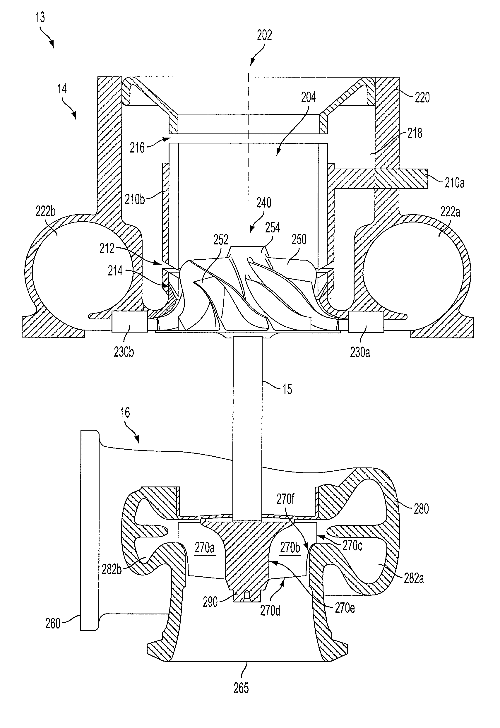
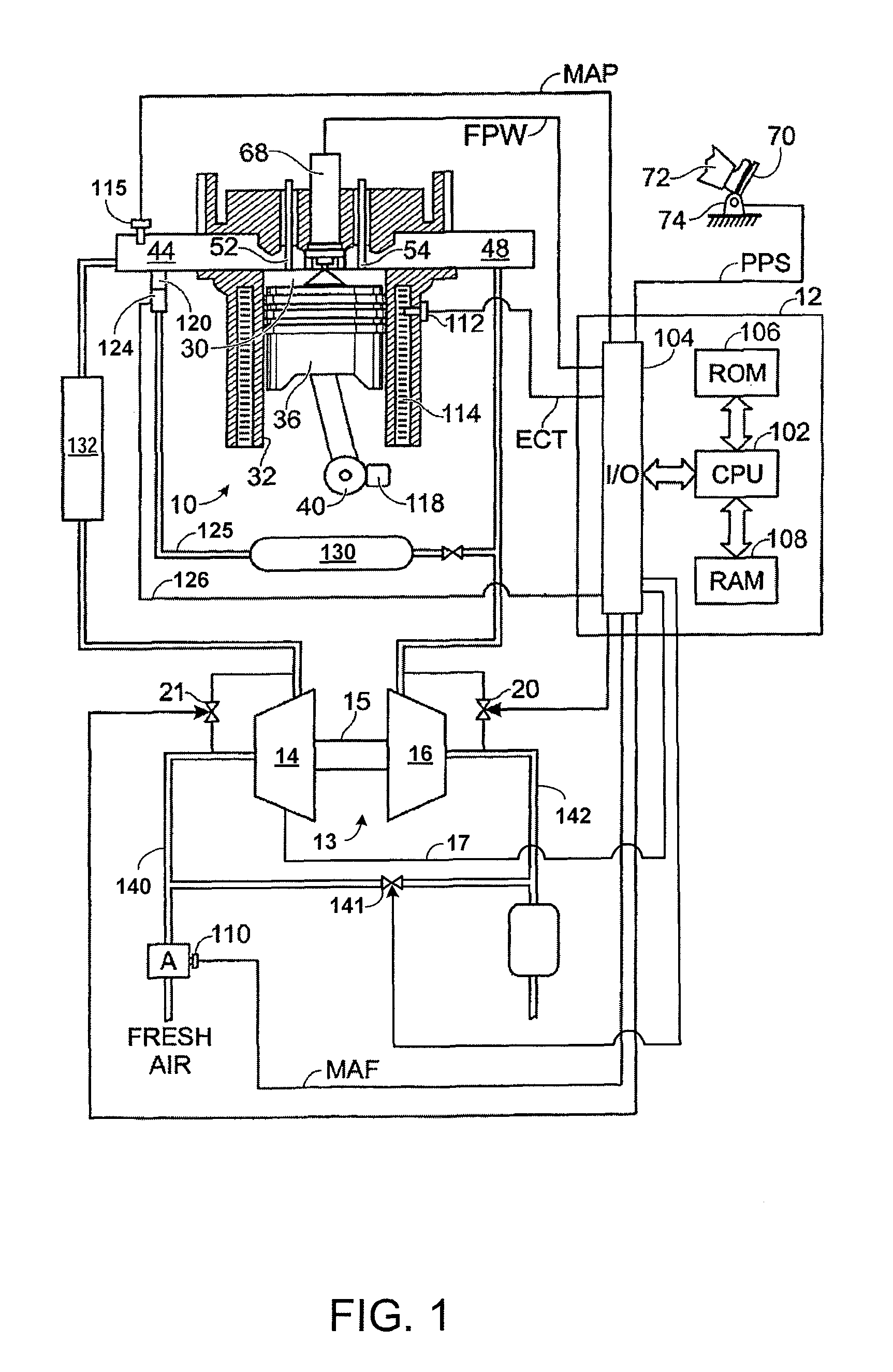
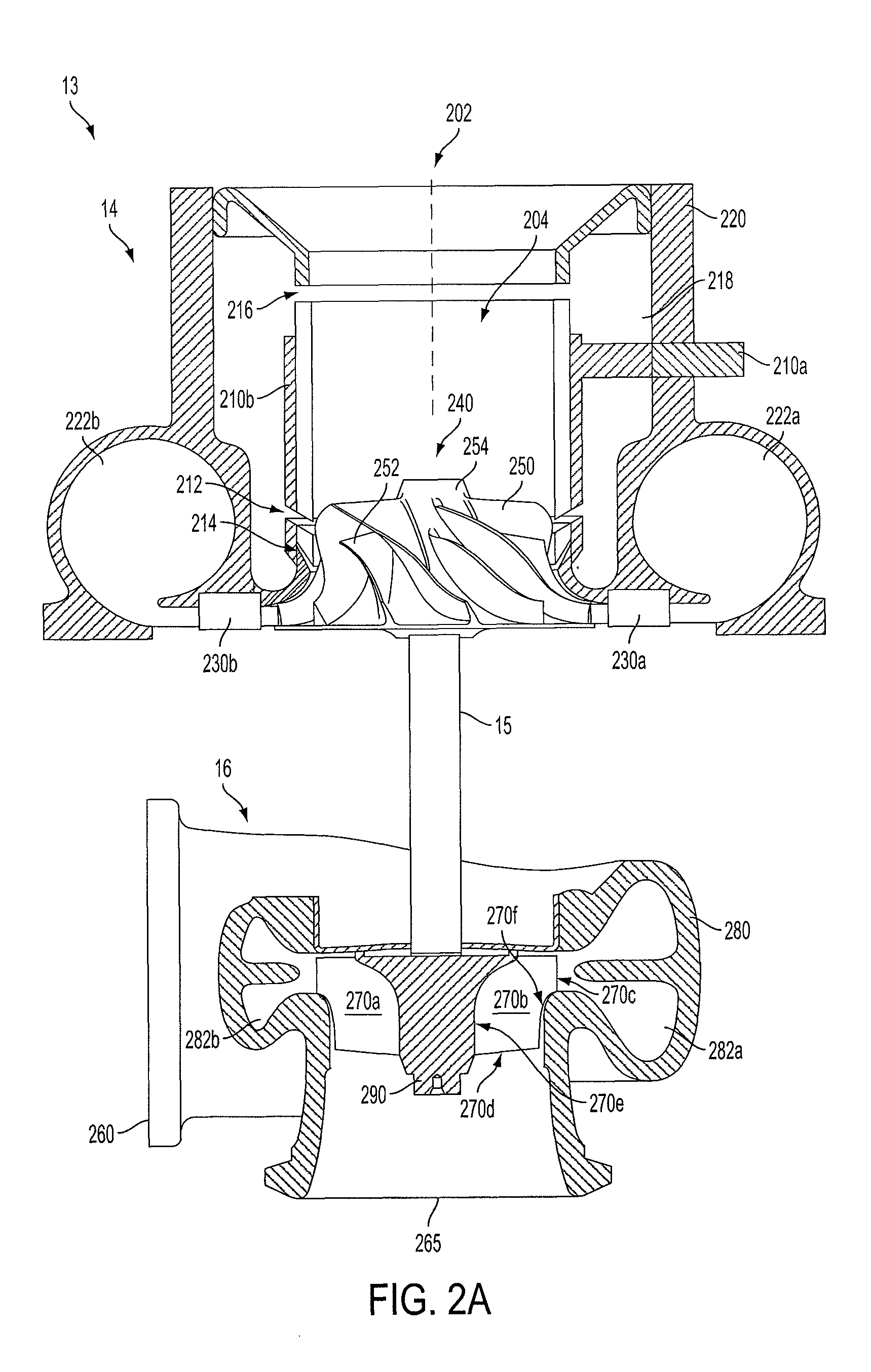
[0024]The following description relates to systems for turbochargers of internal combustion engines with exhaust gas recirculation (EGR). An example embodiment of an engine with a turbocharger and exhaust gas recirculation is illustrated in FIG. 1. The example turbocharger is shown in more detail in FIGS. 2A-2B, such that the components affecting aerodynamic flow through the turbocharger may be examined. In FIG. 2A, a compressor and a turbine in the turbocharger are illustrated. An example embodiment of an impeller blade of a compressor is shown in more detail in FIG. 2A. FIGS. 3A and 3B show a meridional projection of a blade and a cross-section of a blade, respectively, so that various blade characteristics may be defined. FIGS. 4A-4F are tables of prophetic data of impeller blade characteristics that may extend the operating range of the turbocharger. The data from FIGS. 4A-4F are graphed in FIGS. 5A-5B so that generalizations about the data may be observed. FIGS. 6A-6C are table...


PUM


Abstract

In one example, a turbocharger for an internal combustion engine is described. The turbocharger comprises a casing containing an impeller having a full blade coupled to a hub that rotates about an axis of rotation. The casing includes a bleed port and an injection port. The full blade includes a hub edge, a casing edge, and a first distribution of angles, each angle measured between the axis of rotation and a mean line at the hub edge at a meridional distance along the hub edge. The full blade includes a second distribution of angles, each angle measured between the axis of rotation and a mean line at the casing edge at a meridional distance along the casing edge. Further, various systems are described for affecting the aerodynamic properties of the compressor and turbine components in a way that may extend the operating range of the turbocharger.

Description

STATEMENT OF GOVERNMENT CONTRACT[0001]This invention was made under U.S. Government contract No. DE-FC26-07NT43280, Department of Energy.FIELD[0002]The present application relates to systems for turbochargers of internal combustion engines with exhaust gas recirculation.BACKGROUND AND SUMMARY[0003]Engines may use a turbocharger to improve engine torque / power output density. In one example, a turbocharger may include a compressor and a turbine connected by a drive shaft, where the turbine is coupled to the exhaust manifold side and the compressor is coupled to the intake manifold side. In this way, the exhaust-driven turbine supplies energy to the compressor to increase the flow of air into the engine.[0004]The compressor is intended to work in an operating range between two conditions, surge and choke. Surge occurs during low air mass flow, when the air flow through the compressor stalls and may reverse. The reversal of air flow may cause the engine to lose power. One source of surg...

Claims


Application Information

Patent Timeline
Patent Type & Authority Patents(United States)
IPC IPC(8): F04D27/02
CPCF02B47/08F02M25/0707F02M25/0709F04D29/284F04D29/685F04D29/4213F04D29/30F05D2220/40Y02T10/121F02M26/05F02M26/06Y02T10/12
Inventor SUN, HAROLD HUIMINHANNA, DAVEZHANG, JIZHONGHU, LIANGJUNKRIVITZKY, ERIC M.LAROSILIERE, LOUIS M.BAINES, NICHOLAS C.
Owner FORD GLOBAL TECH LLC
Why Eureka
Try Eureka