Optical radiation concentrator

a concentrator and optical radiation technology, applied in the field of devices, can solve the problems of increasing the material content of the components, and achieve the effects of improving the incident angle, improving the performance, and easy changing the thickness of the concentrator

Inactive Publication Date: 2013-08-27
LU ZHENYU +1
View PDF5 Cites 13 Cited by
  • Summary
  • Abstract
  • Description
  • Claims
  • Application Information

AI Technical Summary

Benefits of technology

[0007]In accordance with the present invention, there is provided a spectrally selective planar optical radiation concentrator in which different spectral components of solar energy can be collected for different applications such as heat, illumination and electricity. The planar optical radiation concentrator includes an angle selective optical filter configured to be transparent for incident light within a certain range of incident angles while reflective for radiation having large incident angles exceeding the range, and a light redistribution reflector configured to reflect light with significantly increased incident angle so that light will not be able to escape from the angle selective optical filter. The concentrator of the present invention can also have more components such as a light deflecting component and a fluorescent wavelength shifter to further improve its performance.
[0008]It is an object of the present invention to provide a light-weighted concentrator with only air or vacuum between all of its components while no fill is necessary. The thickness of the concentrator can be easily changed by adjusting the distances of these components. The components of the concentrators are thin films or sheets. Increasing the length and width of the concentrator will only increase the material of those components. If the components are substantially thin, the total weight will not increase much even if the size is significantly increased.
[0009]It is another object of the present invention to provide a concentrator with high concentration ratio and efficiency. The angle selective optical filter will allow light within certain range of incident angles get into the concentrator with very small optical radiation loss. The acceptance angle can be improved by the light deflecting component to eliminate the need for tracking system. Unlike the HPC, the concentrator of the present invention has a light redistributing reflector component which can keep adjusting reflected light to proper directions avoiding light recoupling loss. Therefore, the planar optical radiation concentrator can have a substantially large length in the light guiding direction without sacrificing optical efficiency. Also, because the main media for light to travel in the concentrator is air or even vacuum, the optical loss due to transferring is minimized. As a result, substantially high concentration ratio can be achieved. With high reflectivity of the angle selective optical filter and the light redirecting reflector, high concentration efficiency can also be achieved. The fluorescent wavelength shifter is configured to be transparent and is able to convert ultra-violet radiation to radiant energy with a larger wavelength that can be absorbed by photovoltaic device more effectively, so the overall concentration efficiency can be further improved.
[0010]It is a still further object of the present invention to provide a means for transferring optical radiation. In the present invention, a light transmission pipe can also be realized by those components of the optical concentrator and, therefore, provide a high efficiency light transferring means. By connecting the angle selective filter surface of a light transmission pipe to the exit of an optical radiation concentrator, the concentration ratio can be further significantly improved by transferring radiation energy to the exit of the pipe which is much smaller.

Problems solved by technology

Increasing the length and width of the concentrator will only increase the material of those components.

Method used


Image

  • Optical radiation concentrator
  • Optical radiation concentrator
  • Optical radiation concentrator

Examples


Embodiment Construction

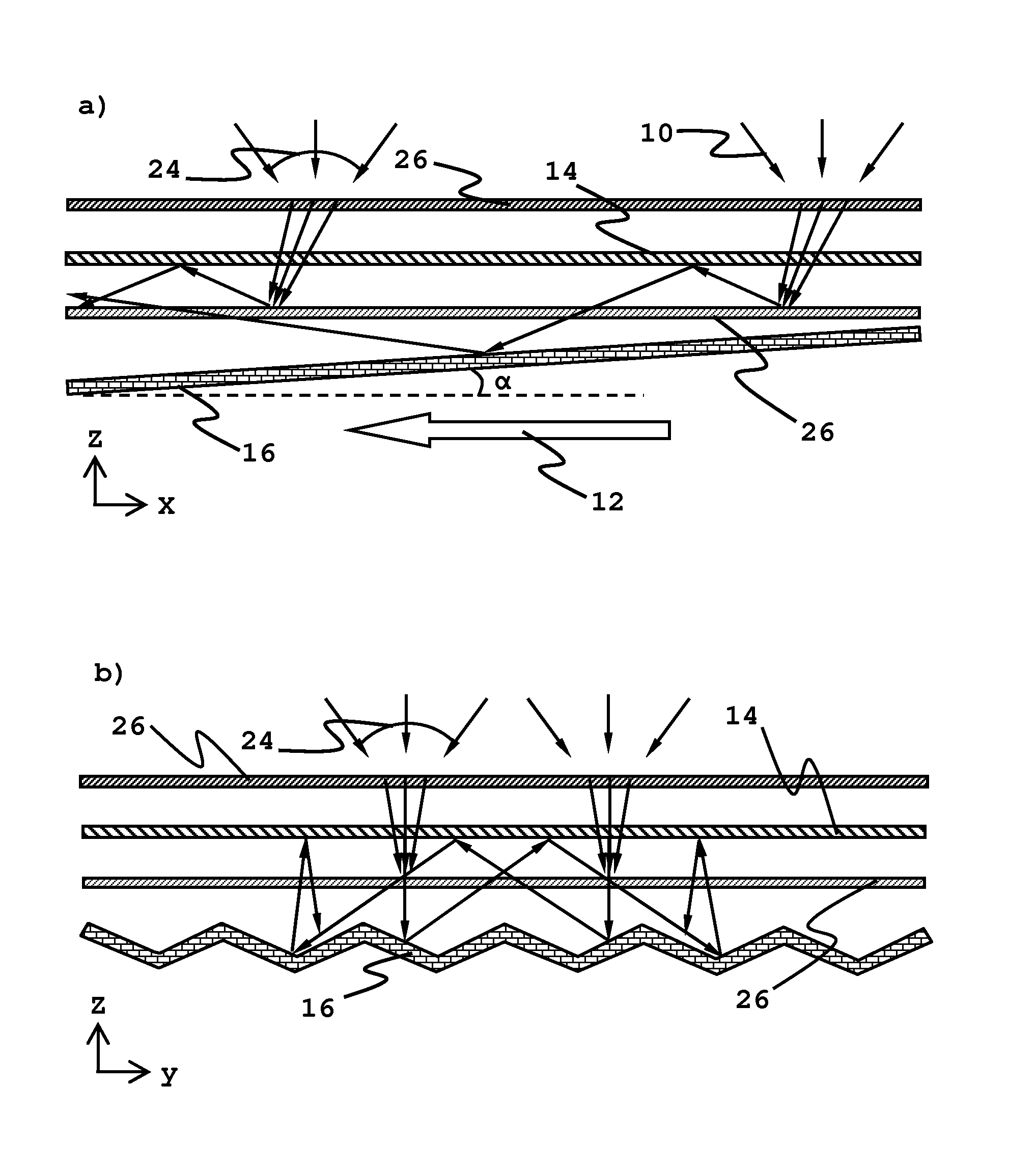
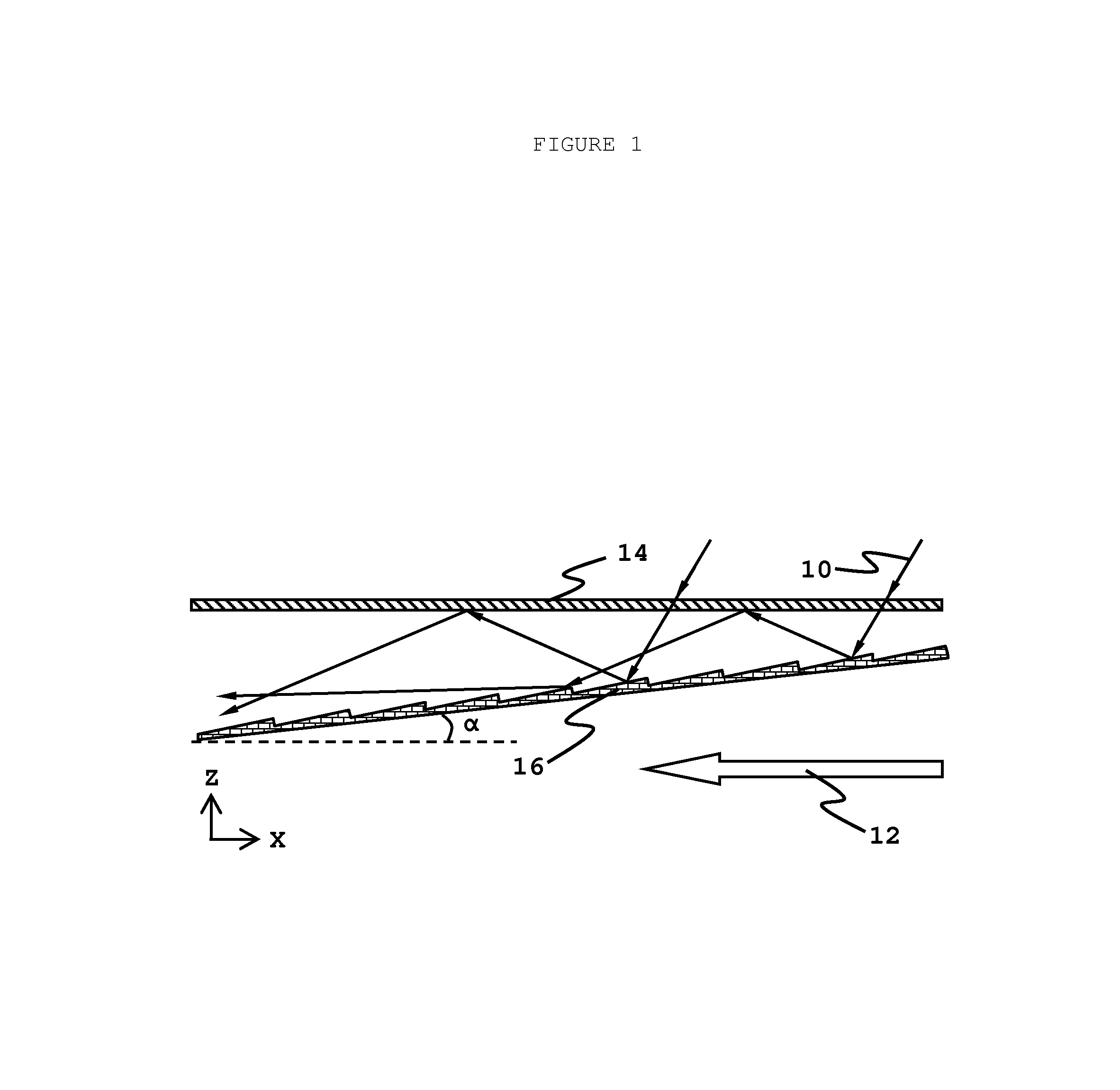
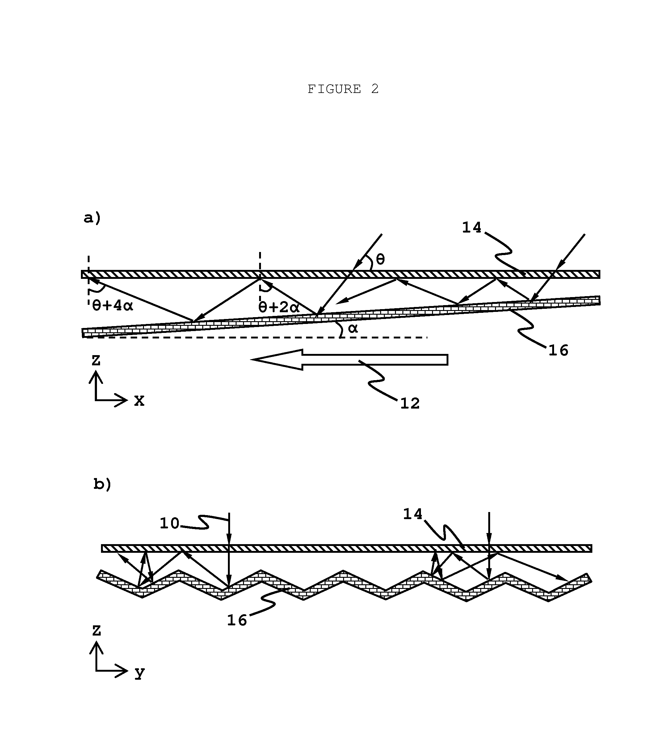
[0029]FIG. 1 shows an embodiment of the optical radiation concentrator 56 which includes an angle selective optical filter 14 and a light redirecting reflector 16. The angle selective optical filter 14 is configured to be transparent for incident light 10 within a certain range of incident angles while reflective for radiation having large incident angles exceeding the range. The light redirecting reflector 16 is configured to reflect light in desired directions, so that the light can have large enough incident angle to the angle selective optical filter 14 and will be reflected by it. As a result, the light is trapped in the optical radiation concentrator 56 and propagating towards a desired light guiding direction 12.

[0030]As shown in FIG. 1, the light redirecting reflector 16 can be a sloped reflecting sheet with small sections further tilted to reflect light with increasing incident angles, so that the light can be trapped and directed closer to a desired light guiding direction...


PUM

PropertyMeasurementUnit
radiant energyaaaaaaaaaa
transmittanceaaaaaaaaaa
reflectanceaaaaaaaaaa

Abstract

The present invention provides a spectrally selective planar optical radiation concentrator, in which different spectral components of solar energy can be collected for different applications such as heat, illumination and electricity. The optical radiation concentrator has two basic components, an angle selective optical filter and a light redistribution reflector for collecting, trapping and concentrating radiant energy. It further comprises a light deflecting component and a fluorescent wavelength shifter to improve acceptance angle and concentration efficiency respectively. The planar optical radiation concentrator exhibits the potential for light weight, high concentration ratio and efficiency, and the ability for passive tracking.

Description

FIELD OF THE INVENTION[0001]The present invention relates to devices for concentrating radiant energy and, more particularly, to optical concentrators for gathering optical radiation energy spanning from the ultra-violet to the infrared.BACKGROUND OF THE INVENTION[0002]Planar shaped solar concentrators have advantages of light weight, compact volume and good compatibility with buildings. However, due to the limitation of shape and material, planar shaped concentrators usually have lower concentration ratio and lower concentration efficiency compared with other types of concentrators such as parabolic concentrator and concentrating lens, etc.[0003]One kind of planar concentrators is luminescent solar concentrator that is typically made of transparent media, such as glass or plastic, containing luminescent material which absorbs solar radiation and emits electromagnetic radiation at a longer wavelength with an isotropic distribution of propagating direction. Most emitted radiation wil...

Claims


Application Information

Patent Timeline
Patent Type & Authority Patents(United States)
IPC IPC(8): G01D5/38
CPCG02B19/0019G02B19/0095G02B19/0042G02B19/009
Inventor LU, ZHENYUYUAN, JINGFENG
Owner LU ZHENYU
Why Eureka
Try Eureka