

Photolytically and environmentally stable multilayer structure for high efficiency electromagnetic energy conversion and sustained secondary emission
a multi-layer structure, high-efficiency technology, applied in the direction of fluorescence/phosphorescence, luminescent dosimeters, optical radiation measurement, etc., can solve the problems of not being able to generate not being able to find high-efficiency materials in the marketplace, and not being able to achieve the wide range of colors. , to achieve the effect of increasing the optical scattering of pumping radiation and/or the emitted radiation, increasing the photolyti
- Summary
- Abstract
- Description
- Claims
- Application Information
AI Technical Summary
Benefits of technology
Problems solved by technology
Method used
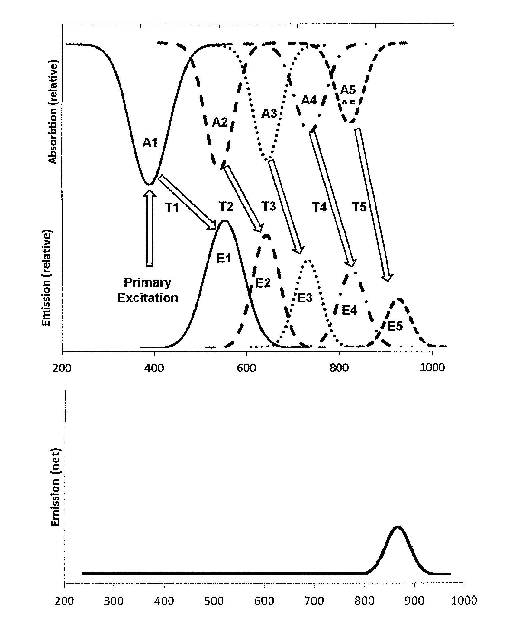
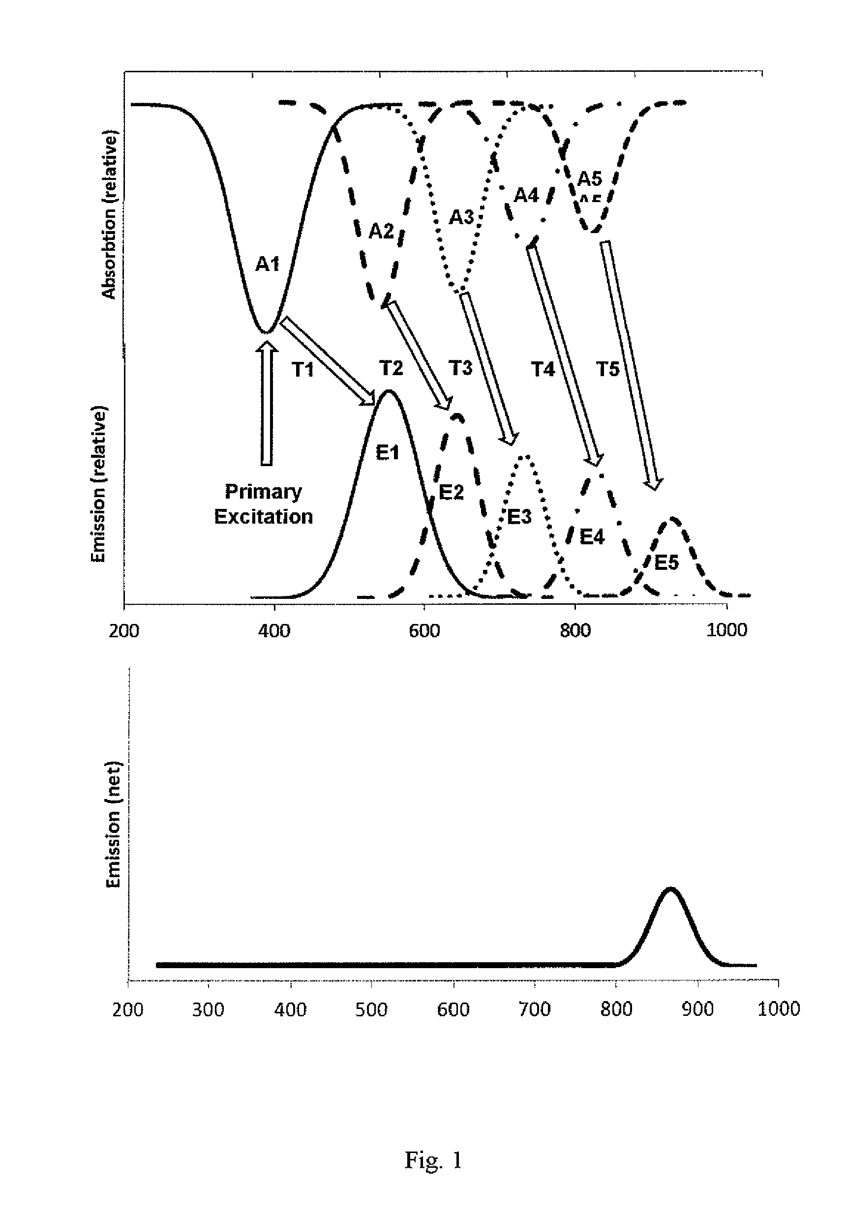
Image

Examples
example 1
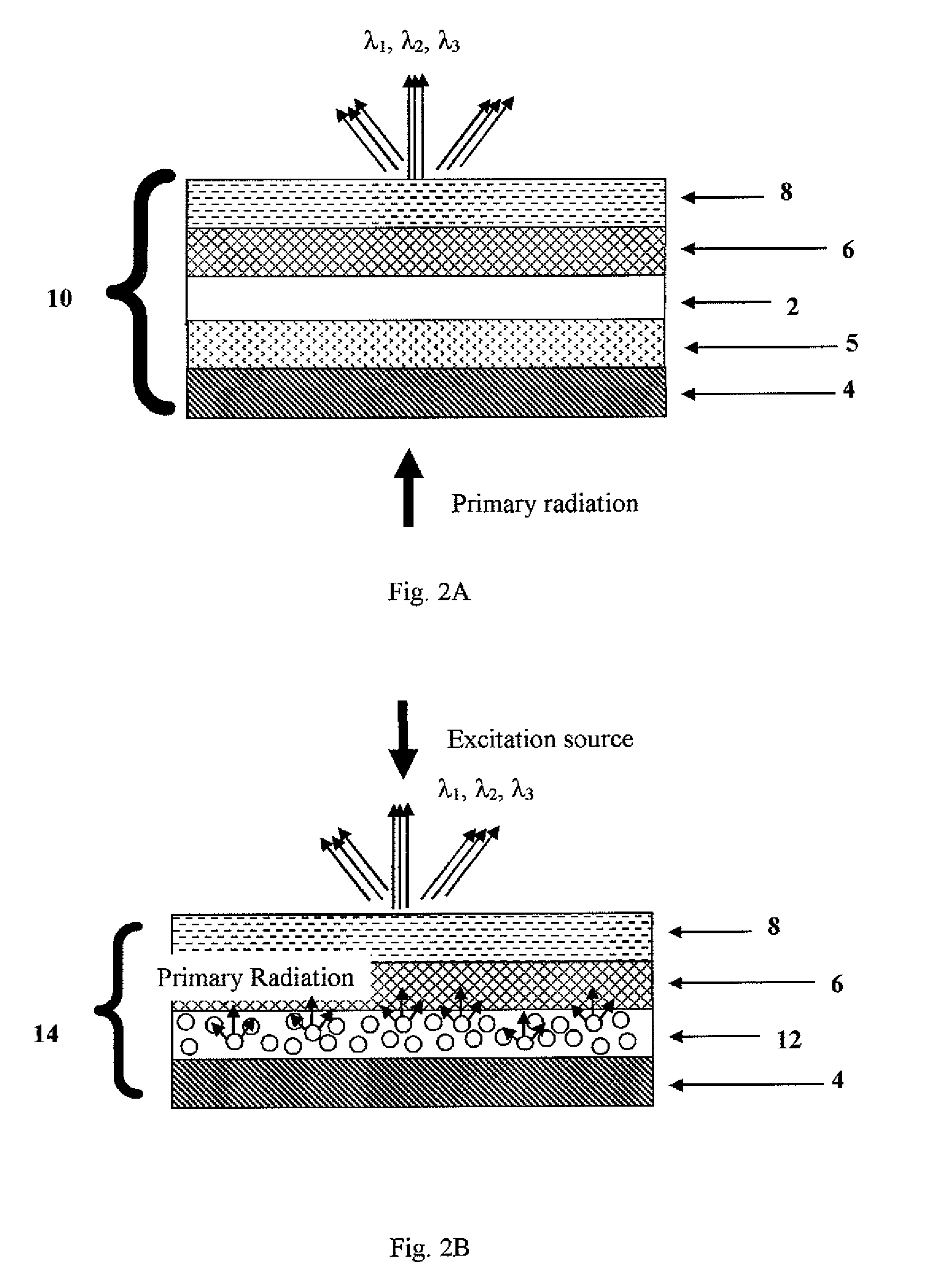
Preparation of Energy Conversion Layer (Characterized as 2 in FIG. 2A)—Film A
[0116]A formulation containing 48 parts of acrylic copolymer, such as Neocryl® B805, 72 parts toluene, 0.125 parts wetting agent, such as Noresil S-900, and 0.626 parts defoamer, such as Foamex N, was prepared and stirred at room temperature. To this solution was added a solution of 0.086 parts 3-cyanoperylene-9,10-dicarboxylic acid 2′,6′-diiosopropylanilide in 4.32 parts dioxolane, and the mixture was stirred until fully dissolved. The formulation was coated on release base at 10 mils or 250 microns wet thickness and dried at 35° C. for 4 hours and then at 80° C. for an additional 12 hours (for ensuring low residual solvent) to yield a 3 mil or 75 micron thick, yellow daylight color film energy conversion layer.
example 2
Preparation of Stability Enhancement Layer (Characterized as 6 in FIG. 2A and FIG. 2B)—Film C
[0117]A formulation containing 20 parts poly(vinyl alcohol) and 230 parts water was prepared and mixed at room temperature, and then heated to 95° C. and slowly stirred for two hours until the solution was clear. The formulation was cooled to room temperature and coated on release base at 10 mils wet thickness, dried at 35° C. for 4 hours and then at 80° C. for 12 hours to yield a 1 mil or 25 microns thick, clear, colorless film.
example 3
Preparation of Protective Layer (Physical & Chemical Protection Together with UV Protection and Other Stabilizing Additives) (Characterized as 8 in FIG. 2A and FIG. 2B)—Film B
[0118]To 403 parts toluene, 1440 grams 4-chlorobenzotrifluoride, and 820 parts methyl acetate was added 28 parts of UV absorber, such as Tinuvin® 405, and the solution was stirred. To the solution at room temperature was added 1440 parts of acrylate copolymer, such as Neocryl® B805, 173 parts plasticizer, such as Plasthall P-670, 4.3 parts wetting agent, such as Noresil S-900, and 17.3 parts defoamer, such as BYK-085, and the mixture was stirred until the components were fully dissolved. The formulation was coated on a release base at 5 mil wet thickness, and the coatings dried at 35° C. for 12 hours to yield a 2 mil or 50 microns thick, clear, colorless film.
PUM
 Abstract
Description
Claims
Application Information