Vehicular camera and lens assembly

a technology of lens assembly and camera body, which is applied in the field of vehicle cameras, can solve the problems of relative cost of components, and achieve the effect of cured relatively quickly

Active Publication Date: 2013-09-24
MAGNA ELECTRONICS INC
View PDF131 Cites 180 Cited by
  • Summary
  • Abstract
  • Description
  • Claims
  • Application Information

AI Technical Summary

Benefits of technology

[0006]In one aspect, the invention is directed to a vehicular camera having a lens that is mounted to a lens holder and is held in position by a selected adhesive. The adhesive is capable of being initially cured relatively quickly by exposure to UV light for supporting the lens relative to the lens holder. The adhesive is further capable of being cured by exposure to a secondary curing condition, such as by exposure to heat, to achieve a fully cured strength, which may take a relatively longer period of time, such as minutes or hours. By providing an adhesive that is initially curable quickly but that reaches a selected fully cured strength and selected performance characteristics, the camera lends itself to having the lens positioned by a robot and then having the adhesive cured quickly to fix the position of the lens so that the camera can be transferred from the robot to a curing fixture for exposure to the secondary curing condition to fully cure the adhesive. Thus, the robot, which may be a relatively expensive component of a system used to manufacture the camera, can be used to adjust the lens of another camera, which may then be transferred to another curing fixture.
[0014]In another aspect, an improved vehicular camera system is provided where the lens resolution is selected to meet but not substantially exceed a resolution determined from the size of a display, a distance between an observer and the display, a selected point on a contrast sensitivity function, and the size of an imager sensing surface.

Problems solved by technology

Thus, the robot, which may be a relatively expensive component of a system used to manufacture the camera, can be used to adjust the lens of another camera, which may then be transferred to another curing fixture.

Method used


Image

  • Vehicular camera and lens assembly
  • Vehicular camera and lens assembly
  • Vehicular camera and lens assembly

Examples


embodiment 1

Use of UV-Curable Adhesive to Mount Lens to Holder

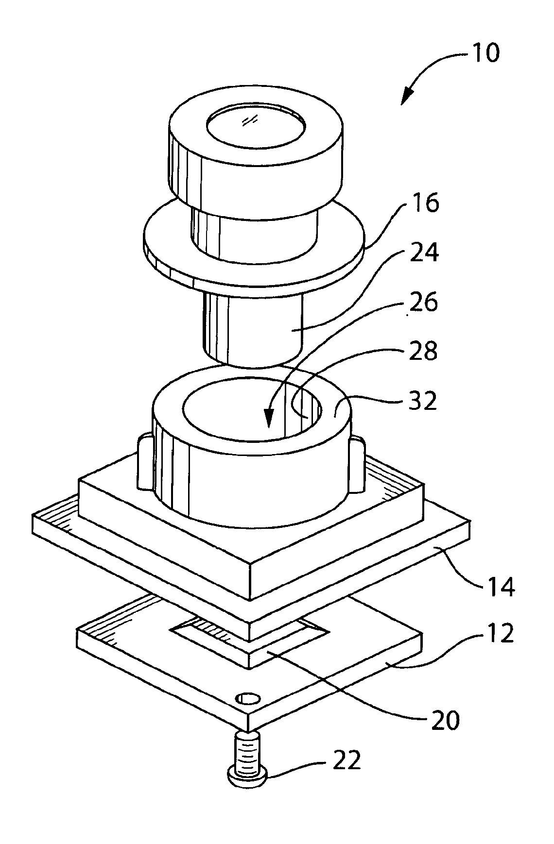
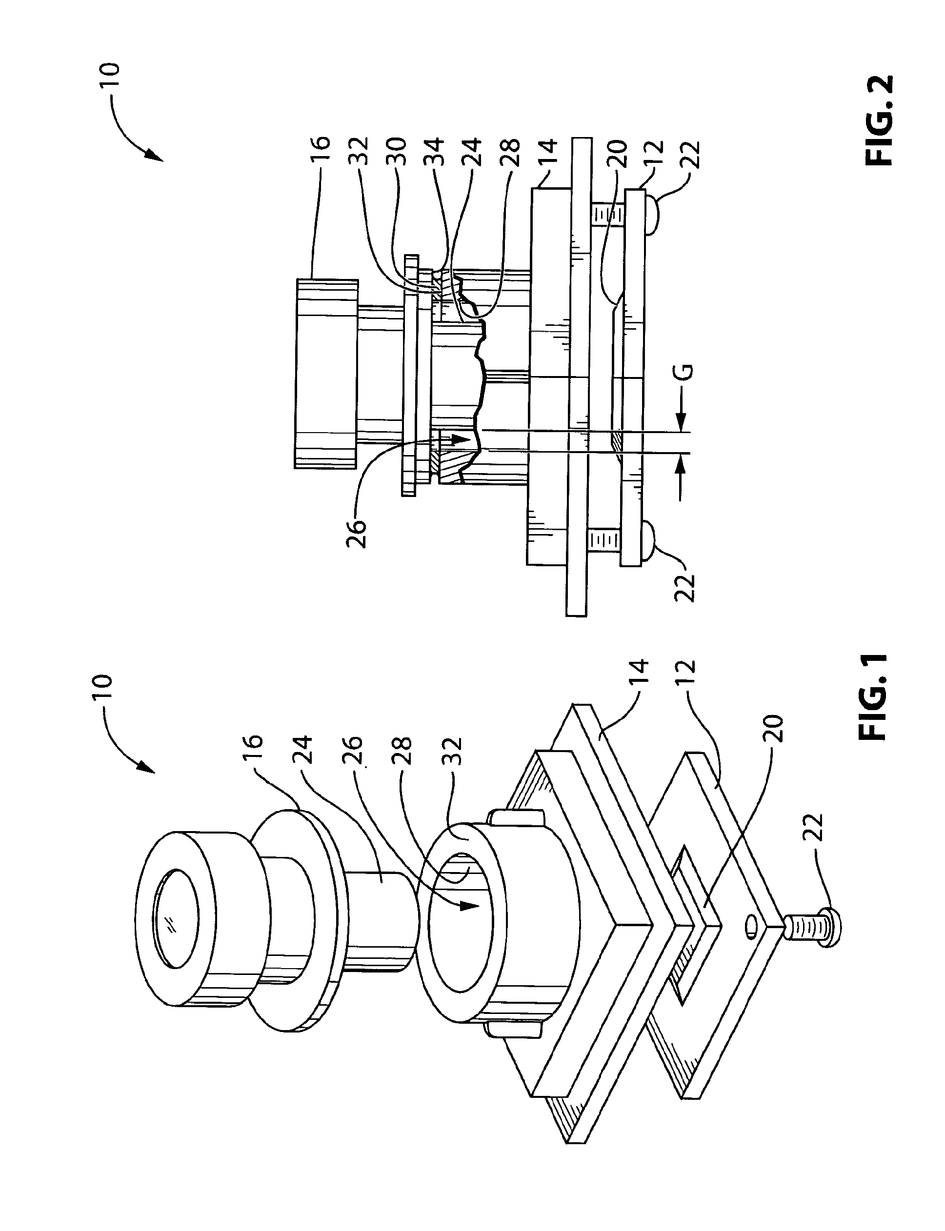
[0034]FIG. 1 shows an exploded view of a vehicular camera 10 in accordance with a first embodiment of the invention. The vehicular camera 10 includes an imager 20, a lens holder such as a front camera housing 14 and a lens 16. The vehicular camera 10 may include other components such as additional circuitry for processing the video input received by the imager 20, e.g., circuitry for providing graphic overlay to the video input. The vehicular camera 10 may further be configured to transmit the video input to other vehicular devices, such as a display controller (not shown) for a cabin-mounted display (not shown).

[0035]The imager 20 may be a charge-coupled device (CCD) or a complimentary metal-oxide semiconductor (CMOS) sensor. Referring additionally to FIG. 2, the imager 20 is mounted to a printed circuit board (PCB) 12. The imager 20 is positioned to receive optical images from the lens 16. In the exemplary embodiment shown in FIG. ...

embodiment 2

Integration of Lens Barrel and Camera Lens Holder

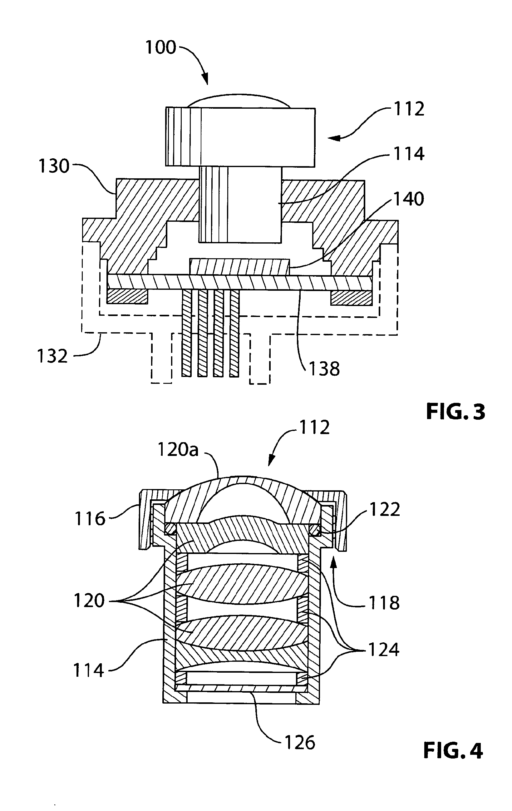
[0047]FIG. 5 shows another embodiment 110 of a vehicular camera, wherein the lens barrel 114 housing the optical components of the lens 112 and the camera front housing 130 form a single integrated piece 150. The lens optical elements 120, O-rings and spacers 122, 124 and IR cutoff filter 126 (FIG. 4) are placed inside a lens barrel portion 114′ of the integrated lens barrel and camera upper housing piece 150 as part of the conventional lens assembly process to provide a lens 112′ (FIG. 5). The integrated piece 150 can be formed by plastic injection molding or metal machining. Plastic injection molding is preferred for lower cost and ease of attaching the back housing 132 to the integrated piece 150 by gluing, laser or ultrasonic welding.

[0048]The PCB 138 with imager 140 is mounted to the integrated piece 110. Lens 112′ is focused relative to the imager 140 by applying techniques described in embodiments 3 to 6.

[0049]The advantages of...

embodiment 3

Lens Barrel Dropped on Surface of Imager

[0050]FIG. 6 shows another embodiment 200 of a vehicular camera wherein the lens barrel 114′ of the integrated piece 150 is dropped onto and sits directly on top of the surface of the imager 140. During the camera assembly process, the lens barrel 114′ is dropped directly onto the imager 140 as shown in FIG. 6. The lens barrel 114′ includes a special designed mechanical feature such as rebate 202 (see detail view of FIG. 6A) so that, while the lens barrel 114′ is dropped to onto the imager 140, the rebate 202 guides the lens 112′ to have proper horizontal alignment such that the lens optical axis is in line with the center of the imager sensing area.

[0051](The alignment of optics axis to the center of the imager can also be achieved by digital shifting of image sensing window on imager. This digital center shifting feature can be found in some imagers, e.g. Aptina MT9V 126 CMOS imager.)

[0052]As shown in FIG. 6, the lens 112′ can be secured by ...


PUM

PropertyMeasurementUnit
temperatureaaaaaaaaaa
humidityaaaaaaaaaa
timeaaaaaaaaaa

Abstract

Low cost constructions of vehicular cameras employ various means for aligning and mounting the camera lens with respect to the imager. Such means include adhesive mounting using a UV curable adhesive, wherein the lens may be focused prior to cure of the adhesive. Other means include directly attaching the lens to the imager by adhesive; integrating the lens barrel and camera lens holder; dropping the lens barrel onto the surface of the imager; focusing the lens utilizing PCB mounting and focusing Screws; and focusing the lens by the relative positioning of camera front and back housings. Costs can also be contained by utilizing matching the resolution of the lens in conformance to human contrast sensitivity function, and by replacing optical chromatic aberration with digital chromatic aberration.

Description

CROSS-REFERENCE TO RELATED APPLICATIONS[0001]This application claims the benefit of U.S. Provisional Application No. 61 / 163,240 filed Mar. 25, 2009 and U.S. Provisional Application No. 61 / 232,544, filed Aug. 10, 2009, the contents of both of which are incorporated herein.FIELD OF THE INVENTION[0002]The invention relates to vehicular cameras, and more particularly, to low cost construction and assembly of such cameras.BACKGROUND OF THE INVENTION[0003]Vehicular cameras are used for a variety of purposes, such as to assist a driver in avoiding obstacles behind a vehicle when backing up, and to detect imminent collisions ahead of the vehicle when driving forward. A vehicular camera includes a lens that focuses video input on an image sensor provided on an imager. In general, the position of the lens relative to the image sensor can impact the quality of the video input received by the image sensor. For example, if the lens is positioned such that the video input is not in focus, then th...

Claims


Application Information

Patent Timeline
Patent Type & Authority Patents(United States)
IPC IPC(8): G02B7/02
CPCG02B7/025G02B7/04G02B13/001G02B27/0025H01L27/14625H04N5/2257G02B7/02H04N5/2253H01L27/14618Y10T29/49002H01L2924/0002H04N23/57H04N23/55H04N23/63H01L2924/00H04N23/51H04N23/54B60R11/04G02B27/62G02B7/003
Inventor LU, YUESHENGBYRNE, STEVEN V.SESTI, MATTHEW C.GIBSON, JOEL S.DEVOTA, ROBERT A.
Owner MAGNA ELECTRONICS INC
Why Eureka
Try Eureka