Air-independent internal oxidation

Active Publication Date: 2013-10-15
ZERE ENERGY & BIOFUELS
View PDF17 Cites 12 Cited by
  • Summary
  • Abstract
  • Description
  • Claims
  • Application Information

AI Technical Summary

Problems solved by technology

Existing external combustion boiler technologies have numerous prob

Method used


Image

  • Air-independent internal oxidation
  • Air-independent internal oxidation
  • Air-independent internal oxidation

Examples


Embodiment Construction

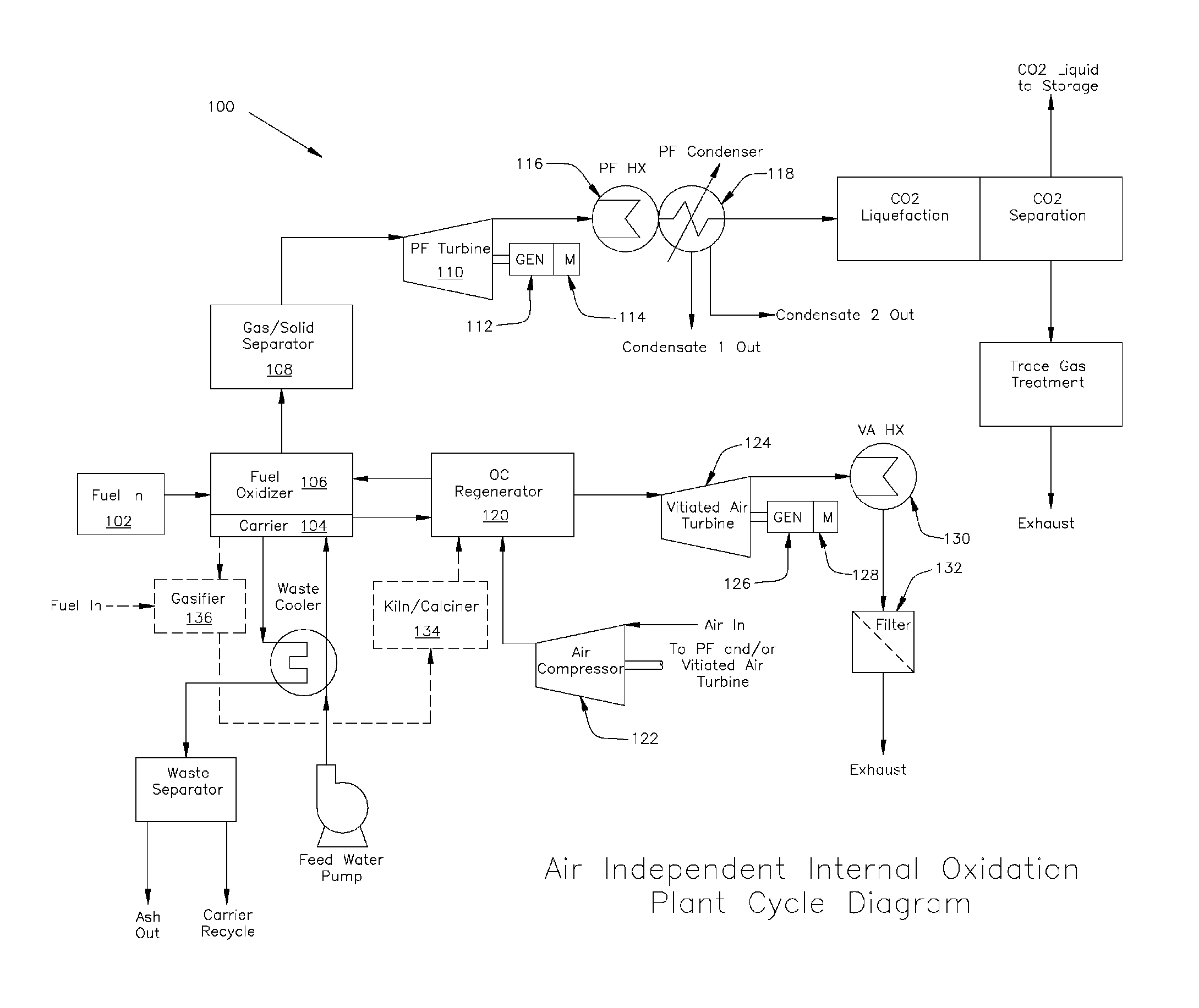
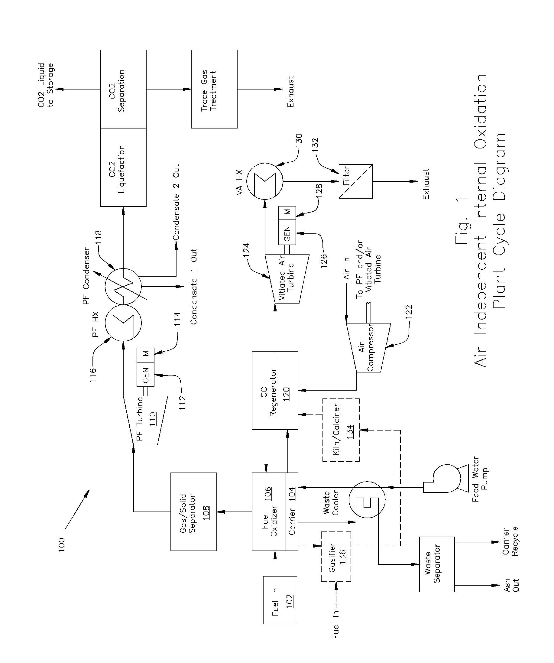
[0017]A dual-reactor chemical-looping combustion system 100, in accordance with an embodiment of the present invention, is shown in FIG. 1. In a preferred embodiment, a fuel 102, which may be in a partially or fully gasified state, is mixed with an oxygen-rich oxygen carrier (typically a metallic oxide or peroxide) in a fluidized bed 104 in a fuel oxidizer 106, as depicted in FIG. 1. (For convenience in drawing, the oxygen carrier is labeled as included in a bed. In alternatives, the oxygen carrier may be in a non-bed form.) The fuel can be any solid, liquid, or gaseous fuel comprised of hydrogen and / or carbon, including coal, natural gas, bio-fuels, land fill gas, and industrial waste gas. The reactions in reactors typically take place at temperatures less than or equal to 1300 degrees C.

[0018]Fuel oxidizer 106 is also called an oxidation chamber. A feedwater pump 103 delivers water to fuel oxidizer 106 for steam production. Carrier 104 oxidizes the fuel and converts its chemical e...


PUM


Abstract

A chemical-looping combustion system is provided in which an oxygen carrier, for example a metallic oxide or peroxide, is used for fuel combustion and produces carbon dioxide and water as by-products. The system delivers steam and CO2 at for direct utilization by steam cycle power generation equipment and heat exchangers. After fuel combustion, the oxygen-poor carrier is regenerated by exposure to air in a second, sequestered reactor. Choice of oxygen-carrier material and conditions allows for the fuel oxidizer reactor to run at temperatures greater than the running temperature of the regenerator reactor.

Description

CROSS REFERENCE TO RELATED APPLICATION[0001]This application claims the benefit of U.S. Provisional Patent Application No. 61 / 131,910, filed Jun. 13, 2008, entitled “Air Independent Internal Oxidation,” Inventor: George Linton Touchton, the disclosure of which is expressly incorporated herein by reference in its entirety.FIELD OF THE INVENTION[0002]The present invention relates to a steam turbine power generation plant system employing a chemical-looping combustion method and to the recovery and utilization of carbon dioxide by-products in the power generation plant system.BACKGROUND OF THE INVENTION[0003]Chemical-looping combustion (CLC) is a flameless combustion technology that requires no direct contact between air and fuel. CLC systems combust carbonaceous or hydrogen fuels by using a solid compound (typically a metal oxide) as an oxygen carrier. The metal oxide is circulated between two reactors: for combustion and regeneration.[0004]In the combustion reactor, the fuel is oxidi...

Claims


Application Information

Patent Timeline
IPC IPC(8): F02G3/00F02C6/00
CPCF02C3/20C01B3/344F22B1/22F22B3/00F01K23/067C10J3/482C10J3/725F02G3/00Y02E20/18C10J2300/093C10J2300/0946C10J2300/0956C10J2300/0976C10J2300/1606C10J2300/1671C10J2300/1675C10J2300/1807C10J2300/1846C10J2300/1884C10J2300/1892C21B2100/62C21B2100/66Y02E20/34Y02P10/32
Inventor TOUCHTON, GEORGE LINTON
Owner ZERE ENERGY & BIOFUELS
Why Eureka
Try Eureka