
System and method of modulating electrical signals using photoconductive wide bandgap semiconductors as variable resistors

a wide bandgap semiconductor and variable resistor technology, applied in electromagnetic wave modulation, optical radiation measurement, instruments, etc., can solve the problems of low radiated energy, communication fratricide, inconvenient use, etc., and achieve linear response, high current, and high current

Active Publication Date: 2013-10-22
LAWRENCE LIVERMORE NAT SECURITY LLC
View PDF12 Cites 10 Cited by
  • Summary
  • Abstract
  • Description
  • Claims
  • Application Information

AI Technical Summary

Benefits of technology

The present invention describes how to use special semiconductor materials to control electrical signals. These materials have the ability to change the way they conduct electricity when exposed to light. This can be done using a compact, stacked structure which allows for the modulation of high voltage signals. The invention can be used in various applications such as high power microwave or RF generation, and energy-modulation of charged particle beams. Different types of semiconductor materials can be used for this invention including silicon carbide, gallium nitride, aluminum nitride, boron nitride, and diamond.

Problems solved by technology

However, because they are operated in avalanche mode this produces broadband, low radiated energy, is not real-time-adaptive, and can cause communication fratricide.
Both of these techniques have inherent problems.
Vacuum electronic devices tend to be bulky and expensive, while nonlinear transmission lines rely on specialized materials which are often difficult to obtain and poorly characterized.

Method used


Image

  • System and method of modulating electrical signals using photoconductive wide bandgap semiconductors as variable resistors
  • System and method of modulating electrical signals using photoconductive wide bandgap semiconductors as variable resistors
  • System and method of modulating electrical signals using photoconductive wide bandgap semiconductors as variable resistors

Examples


example application

ed Particles

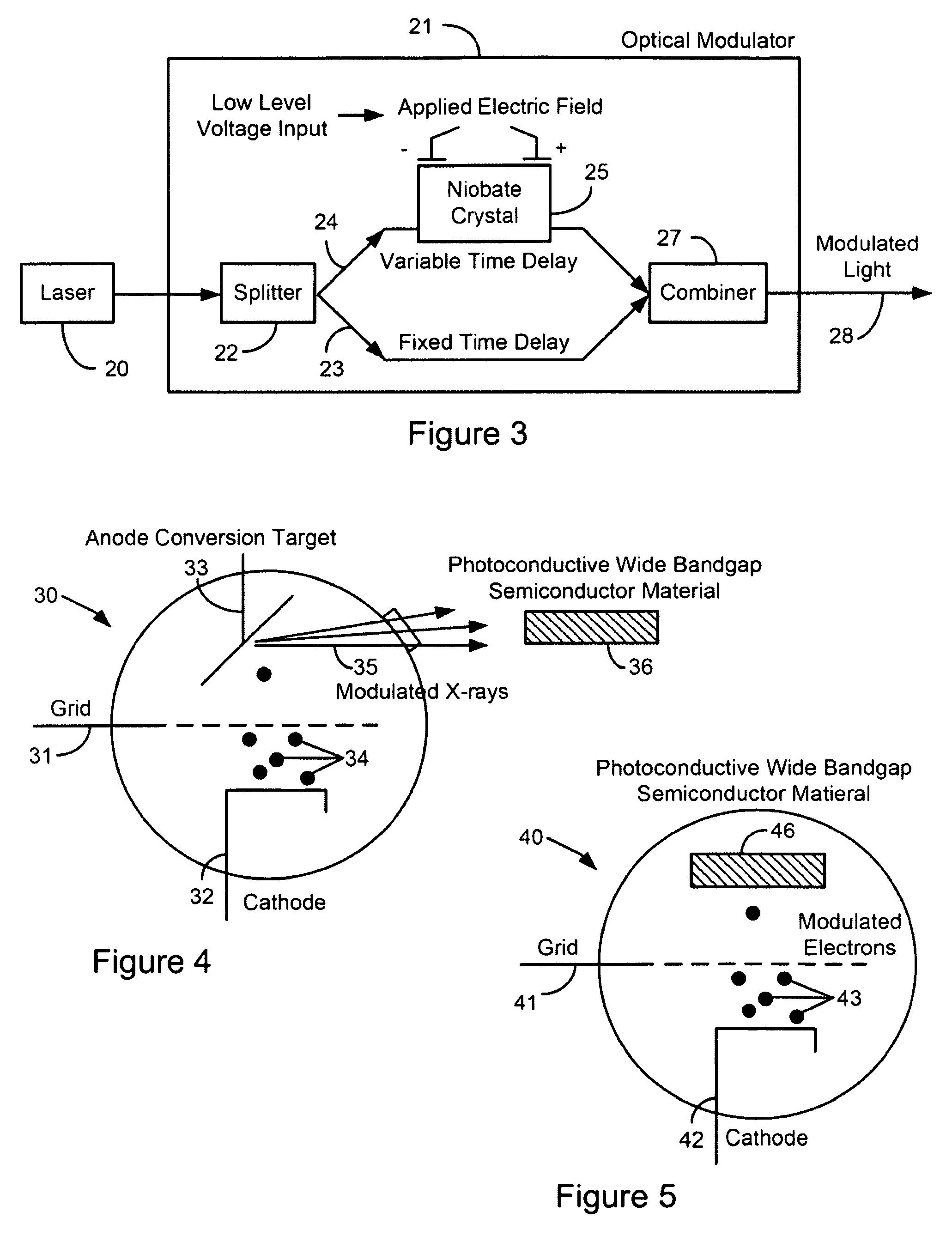
[0052]The modulation of charged particle beams has historically been a critical area of interest. In the case of electron beams, this is especially true, because of the ability of modulated electron beams to produce high-power coherent electromagnetic radiation. Modulation of beams can be divided into density modulation, in which the density of the beam varies along its length, and velocity or energy modulation, in which the energy of a beam (and its velocity, for nonrelativistic beams) varies along its length. A number of techniques have been used to generate modulated beams, such as the use of modulated voltage on grids (as in triodes), or interaction with electromagnetic fields in resonant cavities (such as in klystrons) or slow wave structures (such as in traveling wave tubes). Generally, modulated lasers have not been used to generate modulated particle beams. One exception to this is the use of a modulated laser to produce modulated electron beams through photoemis...


PUM

PropertyMeasurementUnit
dark currentaaaaaaaaaa
currentaaaaaaaaaa
resistanceaaaaaaaaaa

Abstract

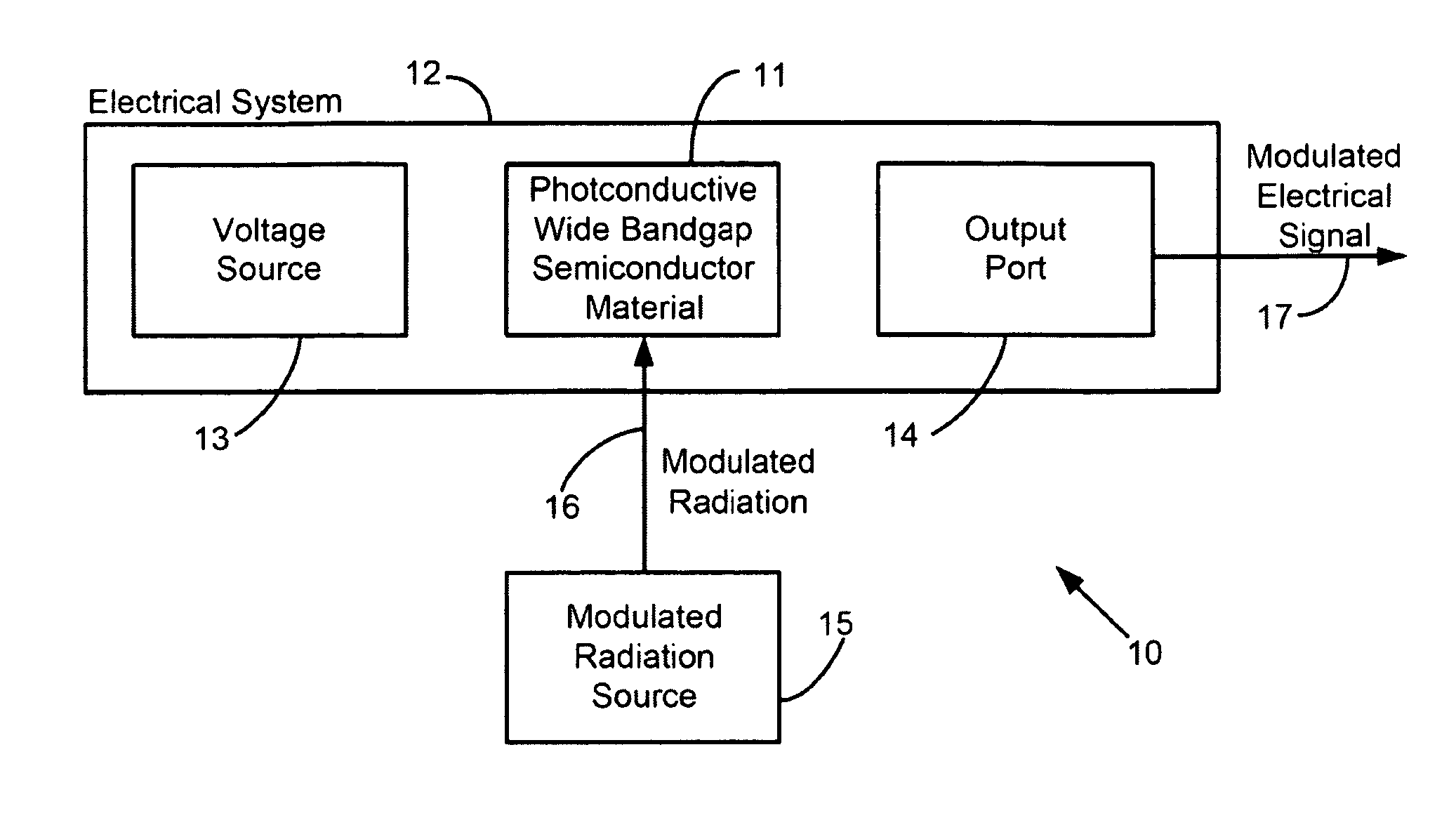
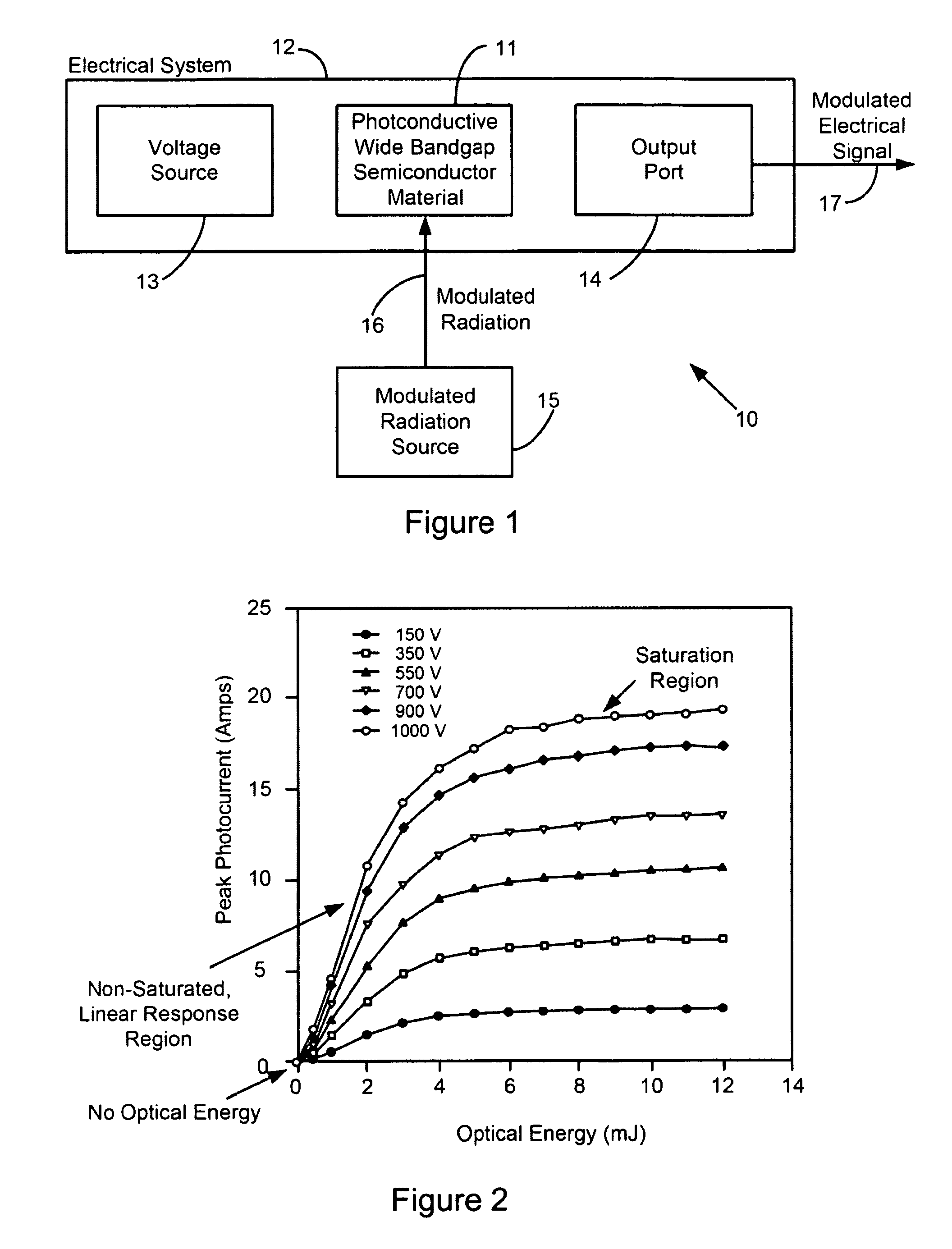
A system and method for producing modulated electrical signals. The system uses a variable resistor having a photoconductive wide bandgap semiconductor material construction whose conduction response to changes in amplitude of incident radiation is substantially linear throughout a non-saturation region to enable operation in non-avalanche mode. The system also includes a modulated radiation source, such as a modulated laser, for producing amplitude-modulated radiation with which to direct upon the variable resistor and modulate its conduction response. A voltage source and an output port, are both operably connected to the variable resistor so that an electrical signal may be produced at the output port by way of the variable resistor, either generated by activation of the variable resistor or propagating through the variable resistor. In this manner, the electrical signal is modulated by the variable resistor so as to have a waveform substantially similar to the amplitude-modulated radiation.

Description

CLAIM OF PRIORITY IN PROVISIONAL APPLICATION[0001]This application claims the benefit of U.S. Provisional Application No. 61 / 045,924 filed Apr. 17, 2009, entitled, “Radiation-modulated Photoconductive Device and System” by John R. Harris et al, and incorporated by reference herein.FEDERALLY SPONSORED RESEARCH OR DEVELOPMENT[0002]The United States Government has rights in this invention pursuant to Contract No. DE-AC52-07NA27344 between the United States Department of Energy and Lawrence Livermore National Security, LLC for the operation of Lawrence Livermore National Laboratory.FIELD OF THE INVENTION[0003]The present invention relates to photoconductive wide bandgap semiconductor materials typically used as solid state switches, and more particularly to the use of photoconductive wide bandgap semiconductor materials as variable resistors operating in non-avalanche mode for producing modulated electrical signals for use in, for example, high frequency modulation applications such as ...

Claims


Application Information

Patent Timeline
Patent Type & Authority Patents(United States)
IPC IPC(8): G01J5/00H01L31/08H01L31/09
CPCH03C1/34H03C7/00
Inventor HARRIS, JOHN RICHARDSONCAPORASO, GEORGE J.SAMPAYAN, STEPHEN E.
Owner LAWRENCE LIVERMORE NAT SECURITY LLC
Learn More