Fast pyrolysis processor which produces low oxygen content, liquid bio-oil

a pyrolysis processor and low oxygen content technology, applied in biofuels, gas dust removal, products, etc., can solve the problem of not knowing of any acceptable means of directly drawing pure oxygen out of high temperature reaction, and achieve the effects of reducing the amount of oxygen bound, minimizing the production of non-condensable gases, and minimizing carbon loss

Inactive Publication Date: 2013-11-05
SINCLAIR DOUGLAS STEWART
View PDF6 Cites 7 Cited by
  • Summary
  • Abstract
  • Description
  • Claims
  • Application Information

AI Technical Summary

Benefits of technology

[0022]Please note, that in our application, although one carbon atom is sacrificed, two oxygen atoms are extracted for each CO2 molecule absorbed by the CaO. The net effect is a reduction in the amount of oxygen bound up in the molecular structure of the pyroly

Problems solved by technology

We do not know of any acceptable means of directly dr

Method used


Image

  • Fast pyrolysis processor which produces low oxygen content, liquid bio-oil
  • Fast pyrolysis processor which produces low oxygen content, liquid bio-oil

Examples


Embodiment Construction

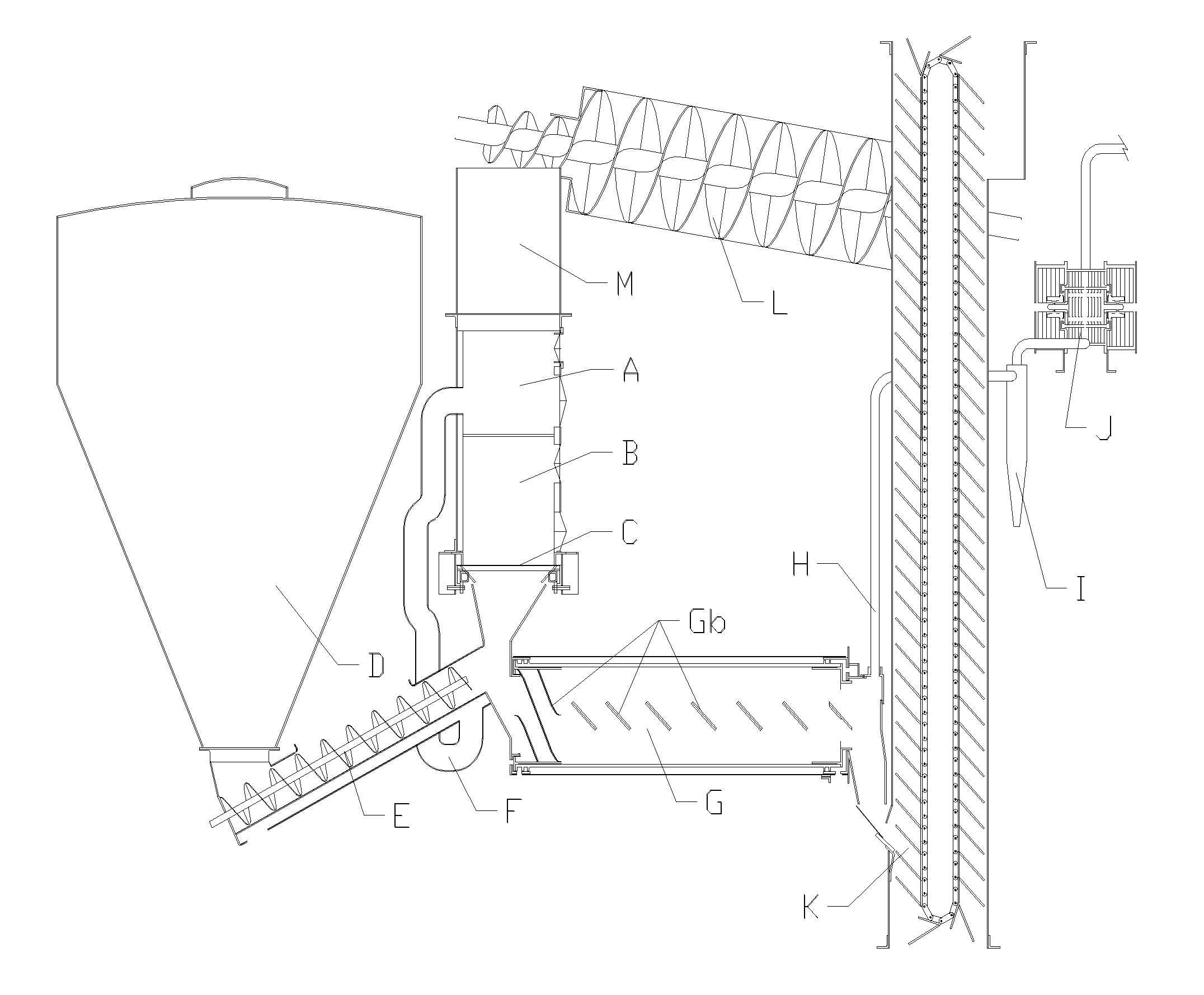
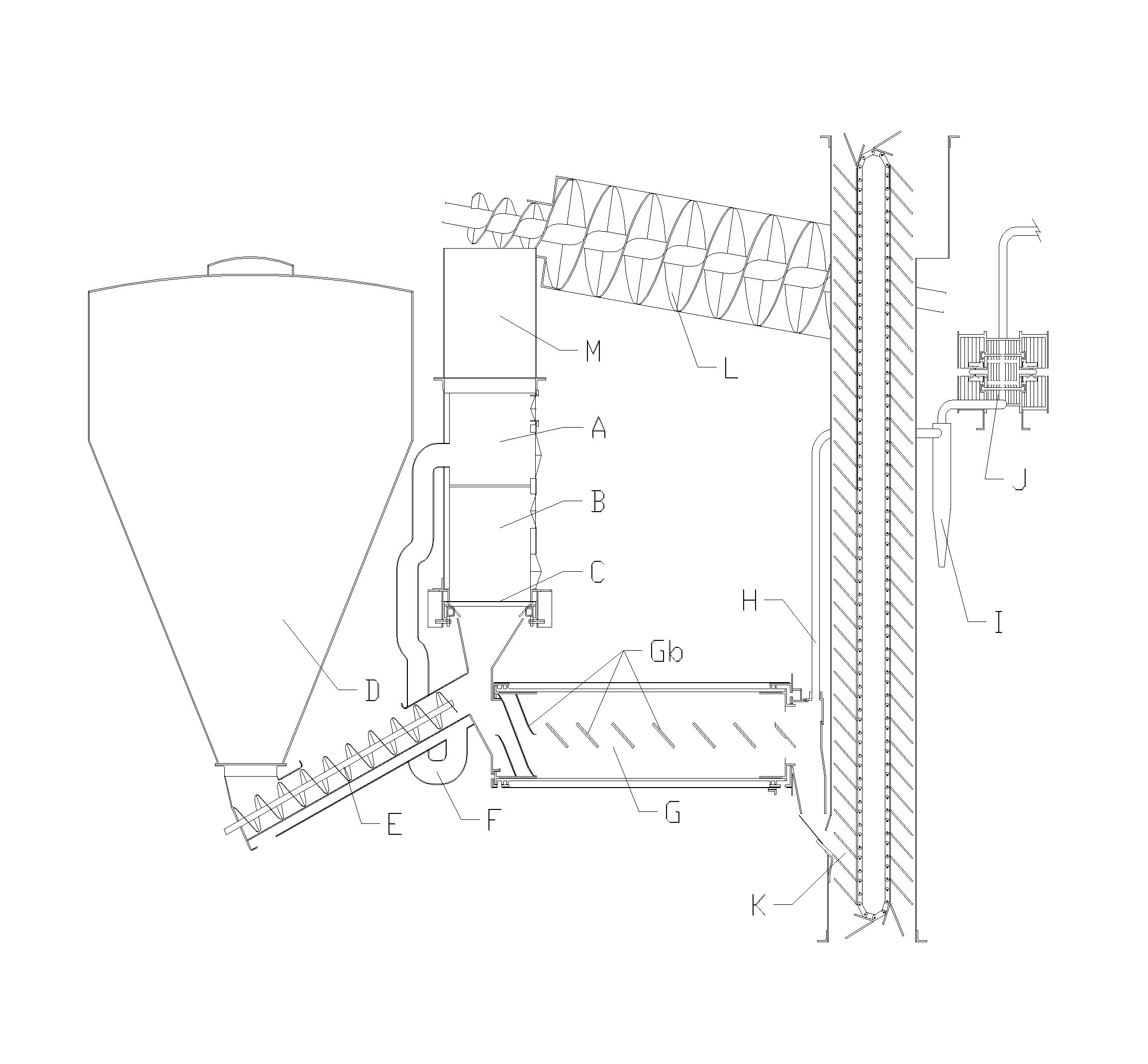
[0039]CaCO3 bearing granular material (hereafter, simply referred to as the “heat carrier”) is calcined in a continuous flow oven (A). The calcined heat carrier flows down into a cooling chamber (B), where it cools down to the pyrolysis temperature. A shuffle tray feeder (C) regulates the flow of the heat carrier into the mixer(G).

[0040]Finely chopped biomass is held in a bulk tank (D), behind the oven. The biomass is dried and conveyed into the pyrolysis chamber by an auger (E), which has an external heating jacket that is heated by exhaust from the calcining oven, carried through pipe(F).

[0041]The dried biomass is mixed with the calcined heat carrier in a rotating drum mixer(G), which serves as the pyrolysis chamber. Inclined bats(Gb), inside the rotating drum mixer, churn the mix and move it forward.

[0042]The pyrolysis gas is drawn out through a pipe (H) from the tail end of the pyrolysis chamber. It is cleaned of ash and char by a hot gas cyclone (I) and then cooled and separate...


PUM


Abstract

In this fast pyrolysis processor the reaction conditions are tailored to minimize the production of gas, while using calcined limestone to provide the heat for fast pyrolysis of biomass and to lower the acidity and oxygen content of the liquid bio-oil which is produced.

Description

CROSS REFERENCE TO RELATED APPLICATIONS[0001]Not ApplicableFIELD OF THE INVENTION[0002]The present invention relates generally to using biomass as a source of renewable energy. In particular the invention relates to the production of low oxygen content pyrolysis oil from biomass.BACKGROUND OF THE INVENTION[0003]Biomass as an energy source is attractive for two main reasons. First, it is renewable. Second, the carbon which makes up the backbone of it's structure is drawn from the air, lowering the carbon dioxide levels which are currently causing great concern for the environment.[0004]Unfortunately, the energy density of biomass is low. It is a bulky commodity which can be expensive to handle and transport. Often the cost of transportation is more than the value of the energy in the biomass. That is why biomass as an energy source is not currently cost competitive with other options available on the energy market.[0005]Numerous methods, such as baling, pelleting, grinding, gasifying...

Claims


Application Information

Patent Timeline
IPC IPC(8): C10B53/02C10G1/02C10B49/18
CPCC10B49/18C10B53/02C10K1/001C10K1/02C10K1/04Y02E50/14C10G2300/1011C10G2300/202Y02P20/145Y02P30/20Y02E50/10
Inventor SINCLAIR, DOUGLAS STEWART
Owner SINCLAIR DOUGLAS STEWART
Why Eureka
Try Eureka