Digital hybrid V2 control for buck converters

a buck converter and digital hybrid technology, applied in pulse generators, pulse techniques, instruments, etc., can solve the problems of limiting the capacitance value that can be provided, load transients, and less than ideal response to load changes of buck converters, so as to avoid pulse skipping oscillation instability, improve transient response, and high sampling rate

Active Publication Date: 2013-11-05
VIRGINIA TECH INTPROP INC
View PDF8 Cites 30 Cited by
  • Summary
  • Abstract
  • Description
  • Claims
  • Application Information

AI Technical Summary

Benefits of technology

[0010]It is another object of the invention to provide a technique and circuit for avoiding pulse skipping oscillation instability without the drawbacks of known techniques and circuits and which can be achieved without inductor current sensing.
[0011]It is a further object of the invention to provide a power converter having a V2 control architecture of improved transient response without requiring high sampling rate or high resolution A / D converters.

Problems solved by technology

However, the response to changes in load of a buck converter is less than ideal and load transients have been generally accommodated by the filter capacitor during the short period required to adjust the duty cycle of the switches to provide more current through the inductor.
Particularly severe load transients are characteristic of digital logic circuits such as processors capable of operating at high clock speeds.
More recently, stringent voltage regulation specifications have required provision of filter capacitors at the point of load where the size of the filter capacitor becomes relatively critical and limits the capacitance value that can be provided.
However, smaller and higher quality (e.g. ceramic) capacitors such as are used at the point of load have a much smaller ESR than large filter capacitors capable of accommodating large load transients as alluded to above.
However, with capacitors that exhibit a very small ESR, the V2 control architecture suffers from pulse-skipping oscillation instability which, as will be discussed in greater detail below, occurs at large load current when the capacitor ripple becomes dominant in the total ripple waveform, particularly in view of the reduced inductor ripple voltage developed when the ESR of the filter capacitor is small.
Several strategies have been developed to eliminate this instability but generally require substantial complexity and critical tuning, even using analog circuits.
Suitable A / D converters may also be susceptible to high frequency noise.
These and other difficulties and complexities have made a digital implementation of a V2 control architecture for power converters, and buck converters in particular, highly impractical.

Method used


Image

  • Digital hybrid V2 control for buck converters
  • Digital hybrid V2 control for buck converters
  • Digital hybrid V2 control for buck converters

Examples


Embodiment Construction

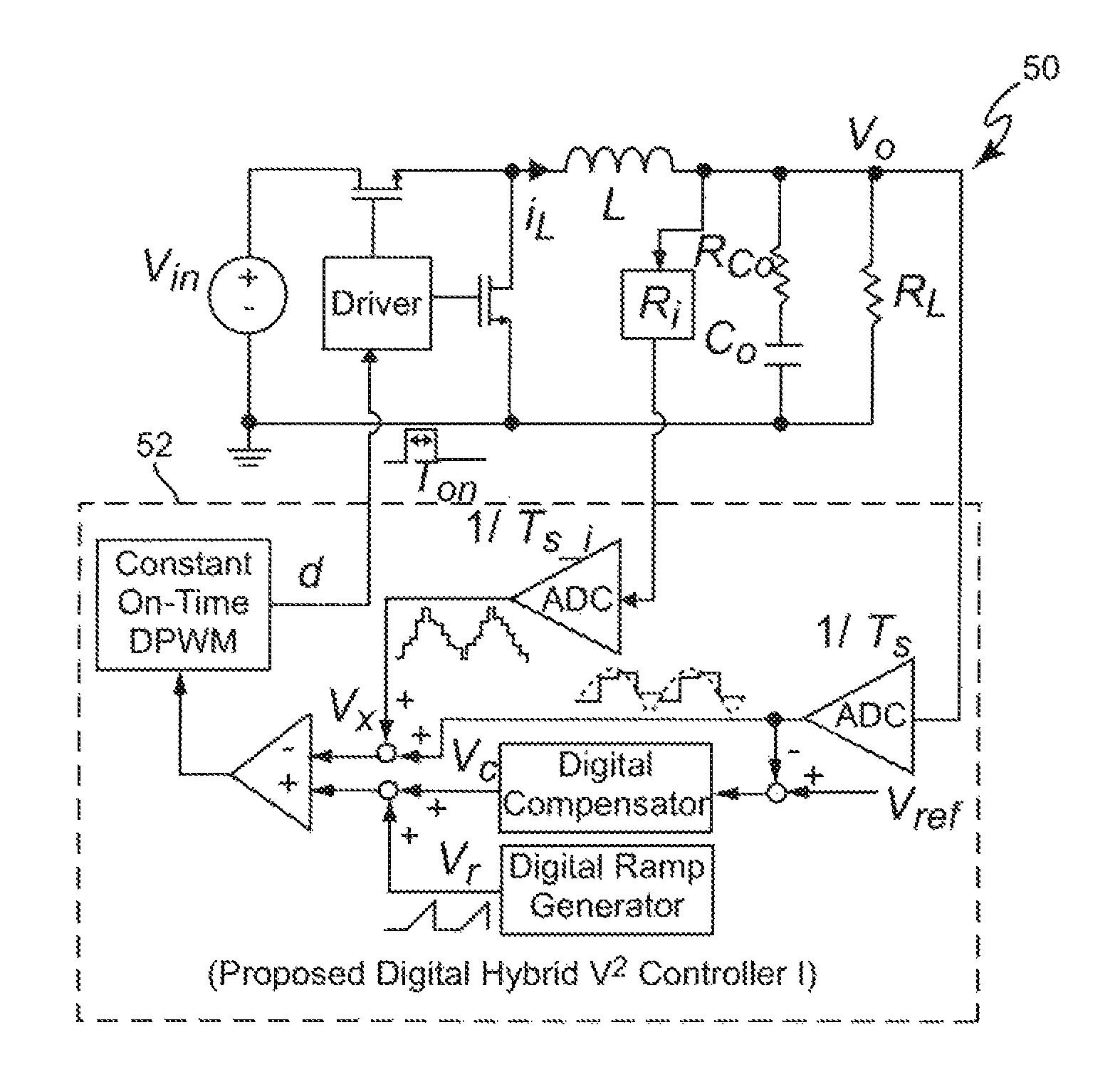
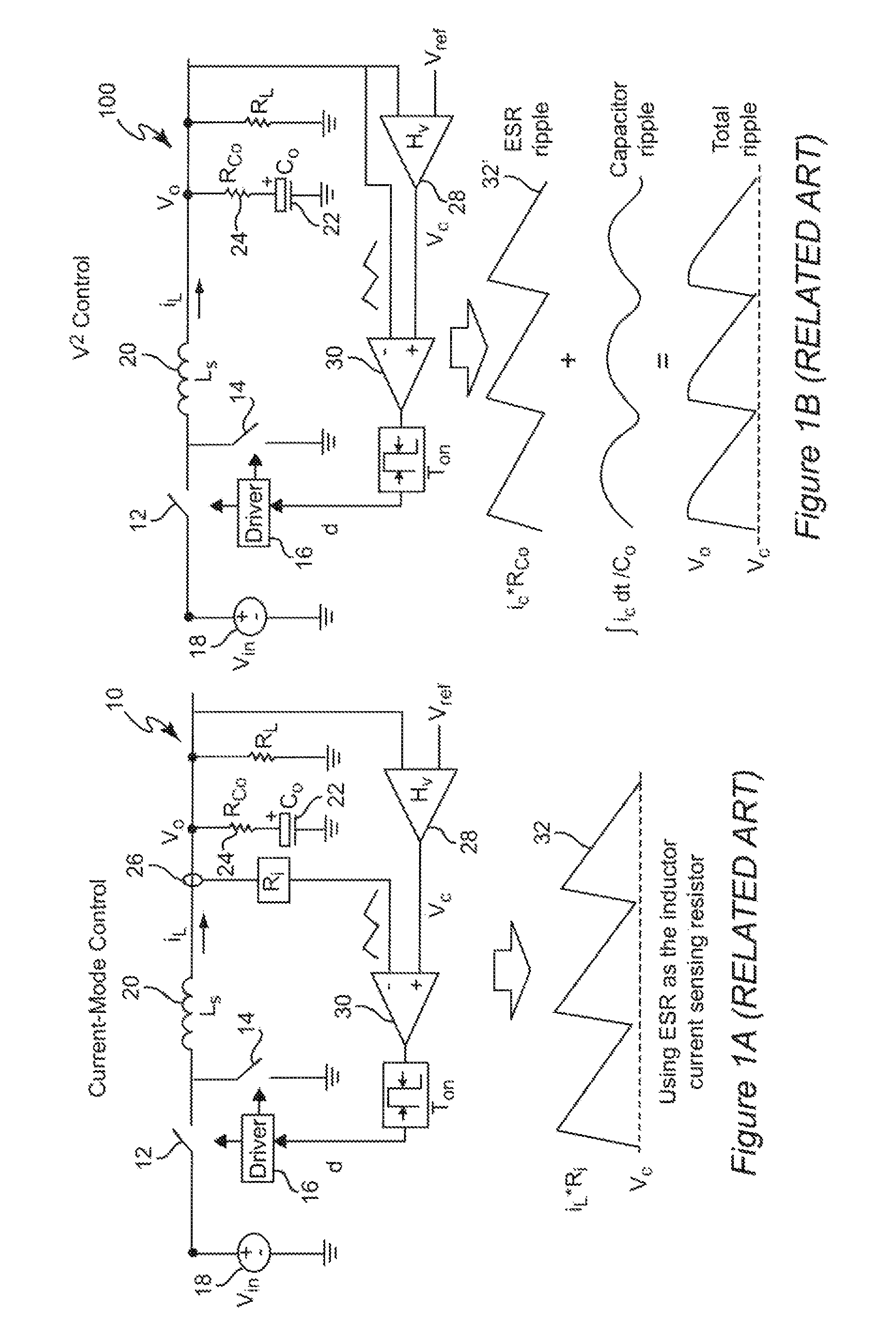
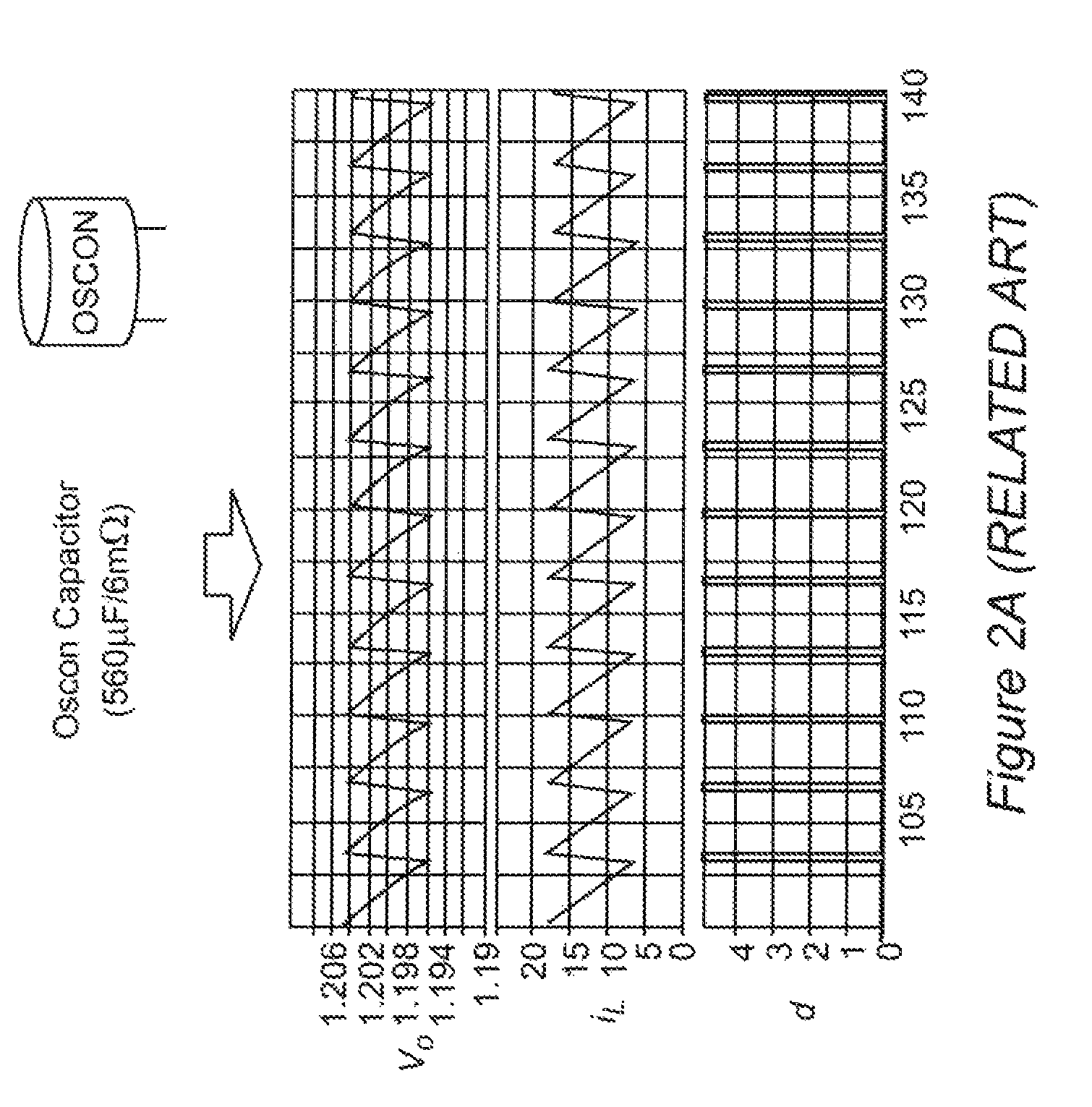
[0028]Referring now to the drawings, and more particularly to FIGS. 1A and 1B, schematic diagrams of buck converters respectively having current-mode control and V2 control are shown. These schematic diagrams are arranged to facilitate an understanding of and appreciation for the invention and no portion of either Figure or FIGS. 2A and 2B is admitted to be prior art in regard to the present invention. It should also be understood that while the invention will be described in connection with a buck converter, the invention is also applicable to other switching power converter topologies. Similarly, for simplicity and to facilitate conveying an understanding of the invention and the problems addressed by it, the invention will be described assuming a constant on-time switching arrangement although the invention is not limited to such an application and constant off-time, constant frequency or other switching schemes or any combination thereof can be employed in the practice of the in...


PUM


Abstract

Stabilization of a switching voltage regulator employing V2 control against ripple oscillation instability when the equivalent series resistance (ESR) of an output capacitor is small is provided by providing both an external ramp and an internal ramp (only the latter of which requires an approximation of inductor current) in the control feedback path, preferably including both inner and outer feedback loops. Approximation of inductor current using such an arrangement is non-critical and may be estimated based on power input voltage. Drift of a circuit providing such an inductor current estimation is preferably avoided by adjusting control duty cycle or slew rate of the positive-going ramp portion of the estimated inductor current triangular waveform.

Description

CROSS-REFERENCE TO RELATED APPLICATIONS[0001]This application claims priority of U.S. Provisional Patent Application Ser. No. 61 / 359,087, filed Jun. 28, 2010, which is hereby incorporated by reference herein in its entirety.FIELD OF THE INVENTION[0002]The present invention generally relates to DC / DC converters and voltage regulating switching power supplies and modules and, more particularly, to power supplies and modules employing V2 control and having output capacitances having small equivalent series resistance (ESR).BACKGROUND OF THE INVENTION[0003]The majority of current and foreseeable electronic devices are designed to operate using direct current (DC) power at a voltage which is substantially constant and often, particularly for modern digital circuits which may be formed as integrated circuits of high integration density, must be very closely regulated even when subject to large changes in load current. To provide such regulation, many different voltage converter topologies...

Claims


Application Information

Patent Timeline
Patent Type & Authority Patents(United States)
IPC IPC(8): G05F1/00
CPCH02M1/14H02M3/1588H02M2001/0012H02M2001/0025Y02B70/1466H02M1/0012H02M1/0025Y02B70/10
Inventor CHENG, KUANG-YAOYU, FENGMATTAVELLI, PAOLOLEE, FRED C.
Owner VIRGINIA TECH INTPROP INC
Why Eureka
Try Eureka