Brushless motor and electric device using same

a brushless motor and electric device technology, applied in the direction of electronic commutation motor control, motor/generator/converter stopper, dynamo-electric converter control, etc., can solve the problems of abnormal sound, deterioration of conductivity of conductive lubricant agent, and corrosion of bearings, so as to reduce the voltage of the shaft

Active Publication Date: 2013-11-19
PANASONIC CORP
View PDF17 Cites 14 Cited by
  • Summary
  • Abstract
  • Description
  • Claims
  • Application Information

AI Technical Summary

Benefits of technology

[0018]With this configuration, since the stator iron core considered as a voltage generator that induces high-frequency voltages to a bearing inner ring and a bearing outer ring is connected to the ground on the drive circuit substrate through the conductive member, the potential of the stator iron core becomes a zero potential, and the shaft voltage can be reduced.

Problems solved by technology

When the shaft voltage reaches a breakdown voltage of an oil film in the bearing, a minute electric current flows in the bearing to cause electric corrosion in the bearing.
When the electric corrosion progresses, a wavelike abrasion phenomenon may occur on a bearing inner ring, a bearing outer ring, or bearing balls to generate abnormal sound, and the abnormal sound is one main factor of drawback in the motor.
However, a conductive lubricant agent is deteriorated in conductivity with elapsed time, and lacks in sliding reliability.
However, this method disadvantageously requires brush abrasion powder or a space.
This method highly effectively suppresses electric corrosion but disadvantageously has high cost.
The method cannot be employed in a general-purpose motor.
For this reason, an imbalanced state occurs, a high shaft voltage is consequently generated.
The high shaft voltage may cause electric corrosion in the bearing.
However, the conventional method as described in Patent Document 1 has the following problem.

Method used


Image

  • Brushless motor and electric device using same
  • Brushless motor and electric device using same
  • Brushless motor and electric device using same

Examples


embodiment 1

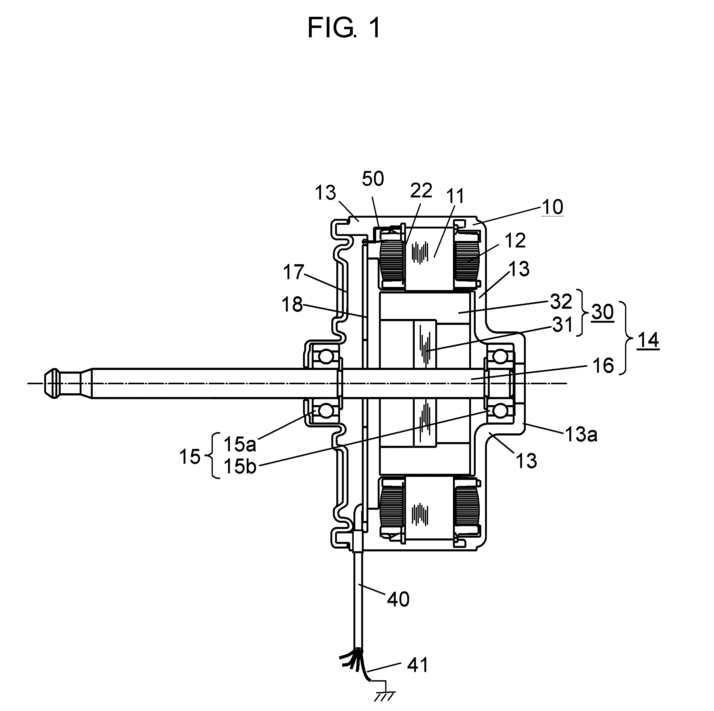
[0025]FIG. 1 is a structural diagram showing a cross section of a motor according to Embodiment 1 of the present invention. In the present embodiment, an example of a motor that is a brushless motor to drive a blowing fan in an indoor unit mounted for an air conditioner serving as an electric device will be described. In the present embodiment, an example of an inner rotor type motor in which a rotor is rotatably arranged on an inner circumference side of a stator will be described.

[0026]In FIG. 1, on stator iron core 11, stator winding 12 serving as a winding is wound on insulator 22 serving as a resin that insulates stator iron core 11. Stator iron core 11 is molded together with another fixing member with insulating resin 13 serving as a molding material. In the present embodiment, the members are integrally molded in such a manner to configure stator 10 having a generally cylindrical shape as an outer shape.

[0027]Inside stator 10, rotor 14 is inserted via a gap (not shown). Roto...

example 1

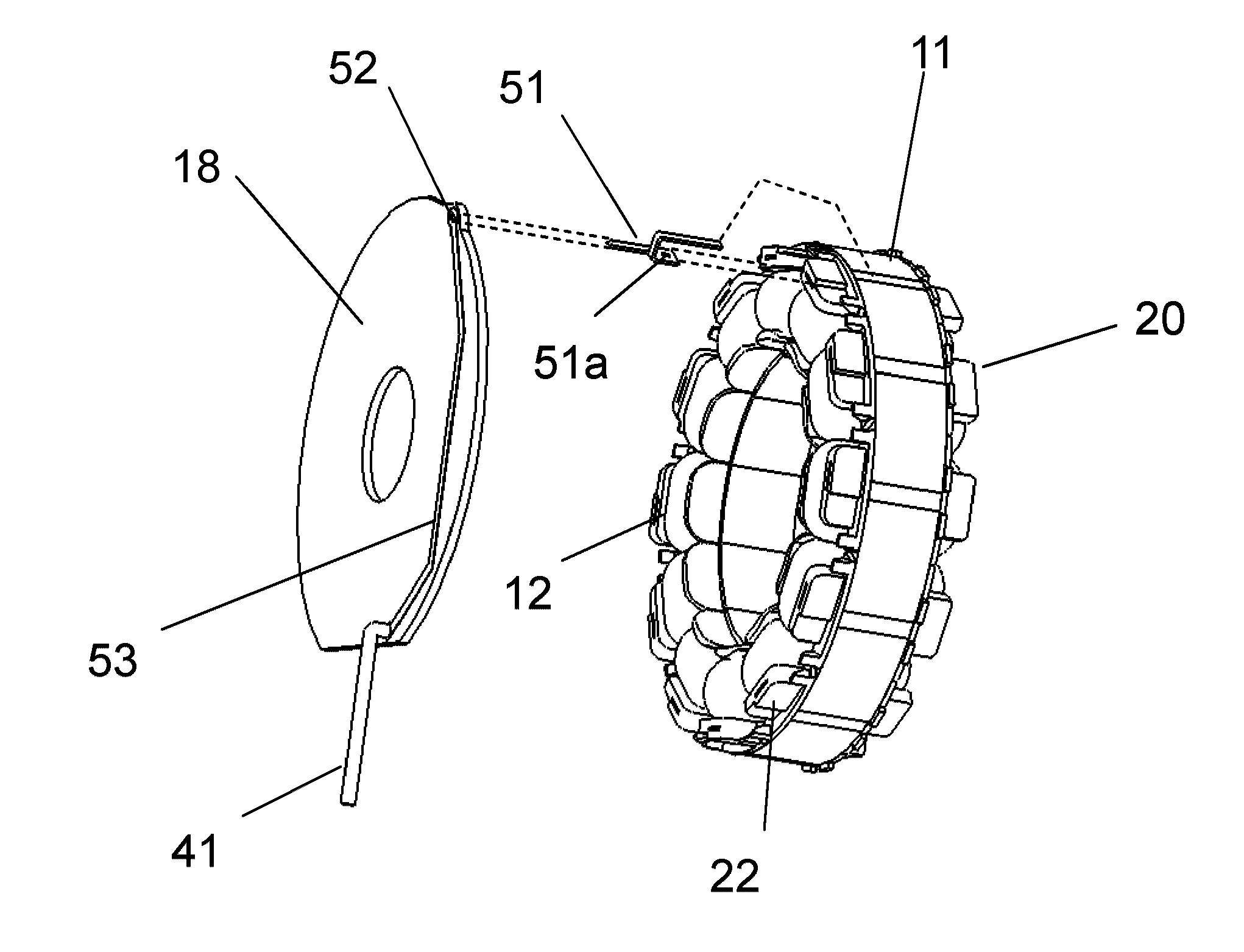
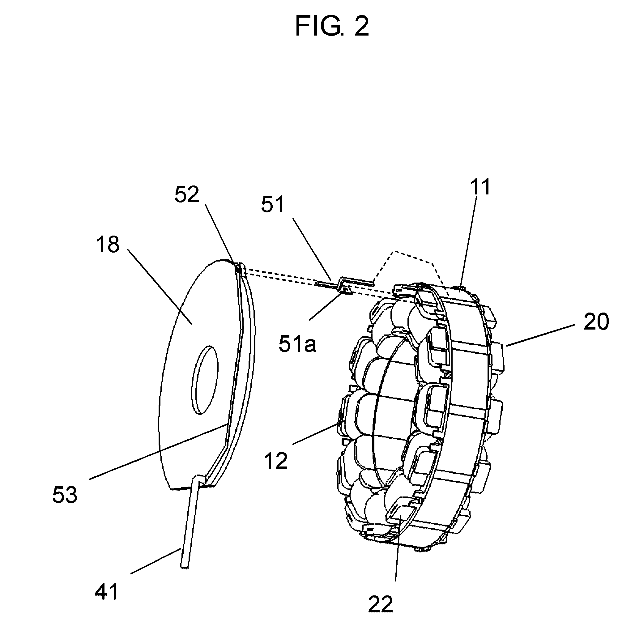
[0049]In the example, a shaft voltage obtained when stator iron core 11 of the brushless motor shown in FIG. 1 was connected to the ground line of drive circuit substrate 18 through conductive member 50 was measured. As a bearing, 608 available from Minebea Co., Ltd. (grease having a consistency of 239 was used) was used.

[0050]FIG. 3 is a diagram showing a method of measuring a shaft voltage in the present example. A DC stabilized power supply was used in a shaft voltage measuring state. The measurement was executed under the same operating conditions in which power supply voltage Vdc of the winding was set to 391 V, power supply voltage Vcc of the drive circuit was set to 15 V, and a rotating speed was set to 1000 r / min. The rotating speed was adjusted by control voltage Vsp, and an attitude of the brushless motor in an operating state was set to make the shaft horizontal.

[0051]In the measurement of the shaft voltage, voltage waveforms were observed with digital oscilloscope 130 (D...

embodiment 2

[0059]FIG. 4 is a diagram showing a configuration of a drive circuit substrate built in a motor in Embodiment 2 of the present invention. Also on drive circuit substrate 18 shown in FIG. 4, as in drive circuit substrate 18 according to Embodiment 1, various electronic parts (not shown) are mounted, and the electronic parts are electrically connected to each other by a wiring pattern pattern-formed with a copper foil on drive circuit substrate 18. The motor according to the present embodiment has the same configuration as that of the brushless motor having the structure shown in FIG. 1, and a detailed description of the motor will be omitted.

[0060]In comparison with Embodiment 1, the brushless motor according to the present embodiment has a characteristic feature in that stator iron core 11 is electrically connected to ground wiring 41 serving as a reference point of a zero potential through iron core connection terminal 51 serving as a conductive member and further capacitor 60. Mor...


PUM


Abstract

A motor includes: a stator molded integrally with an insulating resin having a fixing member including a stator iron core and a winding wound thereon; a rotor arranged to face the stator about a shaft; a bearing rotatably supporting the shaft; a bracket fixing the bearing; and a drive circuit substrate having a drive circuit mounted thereon for driving the winding. The stator iron core is electrically connected to a ground serving as a reference point of a zero potential on the drive circuit substrate through a conductive member.

Description

[0001]This application is a 371 application of PCT / JP2009 / 006779 having an international filing date of Dec. 11, 2009, which claims priority to JP2008-315365 filed on Dec. 11, 2008, the entire contents of which are incorporated herein by reference.TECHNICAL FIELD[0002]The present invention relates to motors and, more particularly, to a motor that is improved to suppress electric corrosion from occurring in a bearing.BACKGROUND ART[0003]In recent years, a motor has often employed a method in which a motor is driven by an inverter using a pulse width modulation system (to be referred to as a PWM system hereinafter). In the inverter driving of the PWM system, since a neutral-point potential of a winding is not zero, a potential difference (to be referred to as a shaft voltage hereinafter) is generated between an outer ring and an inner ring of a bearing. The shaft voltage includes a high-frequency signal obtained by switching. When the shaft voltage reaches a breakdown voltage of an oi...

Claims


Application Information

Patent Timeline
Patent Type & Authority Patents(United States)
IPC IPC(8): H02K11/00H02P25/08H02P6/10
CPCH02K5/08H02K11/0073H02K11/0089H02K5/1732H02K5/225H02K2211/03H02K11/33H02K11/40
Inventor KADO, HARUHIKOWATANABE, AKIHIKOMIZUKAMI, HIROFUMIHASEGAWA, TAKEHIKO
Owner PANASONIC CORP
Why Eureka
Try Eureka