Method and apparatus for dynamic image registration

a dynamic image and registration method technology, applied in the field of image co-, can solve the problems of not being able to mechanically match these axes, requiring a more complex calibration procedure, and the relative orientation of the two cameras is more complicated, so as to reduce or virtually eliminate the drift refine the registration more finely, and reduce the effect of intrinsic sensor nois

Active Publication Date: 2013-11-19
EQUINOX CORP
View PDF6 Cites 41 Cited by
  • Summary
  • Abstract
  • Description
  • Claims
  • Application Information

AI Technical Summary

Benefits of technology

[0008]One critical aspect of the proposed system design is the ability to register synchronized imagery between two video camera sensors. Specifically, we must be able to locate the (smaller) field-of-view camera sensor within the wider field-of-view camera. As this setup can be considered a generalized version of a stereo vision rig, the desired registration can be computed by calibrating it as such. We perform this calibration by measuring the intrinsic camera parameters for each sensor in the laboratory, and deducing relative camera orientations in real-time by using the Inertial Measurement Unit (IMU) devices mounted rigidly to each sensor-attached three dimensional frame. The computation of intrinsic camera parameters can be done in the laboratory by imaging a calibration pattern and applying any of a number of standard camera calibration algorithms [2]. This allows us to recover features such as the effective focal length of each camera system, and the location of their principal points on the respective focal plane arrays.
[0012]A prevalent behavior of IMU orientation sensors is that they drift over time so that image registration from IMU relative orientation calibration becomes more and more inaccurate and sometimes even unreliable. However, when there is significant overlap in the field-of-views of both cameras using additional information provided by matching image features between the two cameras reduces or virtually eliminates this drifting. The IMU and image feature registration work synergistically in that the IMUs provide at least coarse relative orientation information between the two cameras while image feature matching refines the registration more finely. Furthermore image registration reduces the effect of intrinsic sensor noise in the IMUs themselves. When there is significant overlap in field-of-view between both cameras, image feature matching alone (i.e., without IMU information) can bring the images into co-registration. There is certainly relevant application of this invention to the special case where the two cameras are in fact co-located, boresighted and have similar fields-of-view, such as for the U.S. Army ENVG-D and related programs, where automatic co-registration can be performed without the use of IMUs.
[0013]In terms of user interface, the system provides the user with an integrated view from his sensors, and the ability to switch between a few simple visualization modes. In a default setting for a rifle mounted thermal image weapon sight, the aim point reticle is overlayed on the view from the helmet-mounted visible intensified camera sensor, in its correctly registered location. For another setting the thermal weapon sight image is opaquely overlayed, and yet another setting the thermal weapon sight image is pixel fused where overlapping the helmet mounted camera. At no point during this process does the user need to bring the weapon up to the shoulder in order to engage the target, since the sight's reticle is clearly seen on the helmet mounted camera field of view. This constitutes a completely seamless transition from navigation to target detection and finally target engagement, all the while keeping the weapon slung and weight-relieved at the side.

Problems solved by technology

Recovery of the relative orientation of the two cameras is more complicated and requires a more complex calibration procedure.
The main difficulty stems from the fact that the principal axis of each imaging device does not generally coincide with any canonical orientation axis of the IMU devices.
This is a side-effect of the fact that we are limited in our options for mounting each device on their respective platforms, and thus we have no way of mechanically matching these axes.
Given the laws of perspective imaging, there is no way to completely solve this problem, so we must work with the distant target assumption.

Method used


Image

  • Method and apparatus for dynamic image registration
  • Method and apparatus for dynamic image registration
  • Method and apparatus for dynamic image registration

Examples


Embodiment Construction

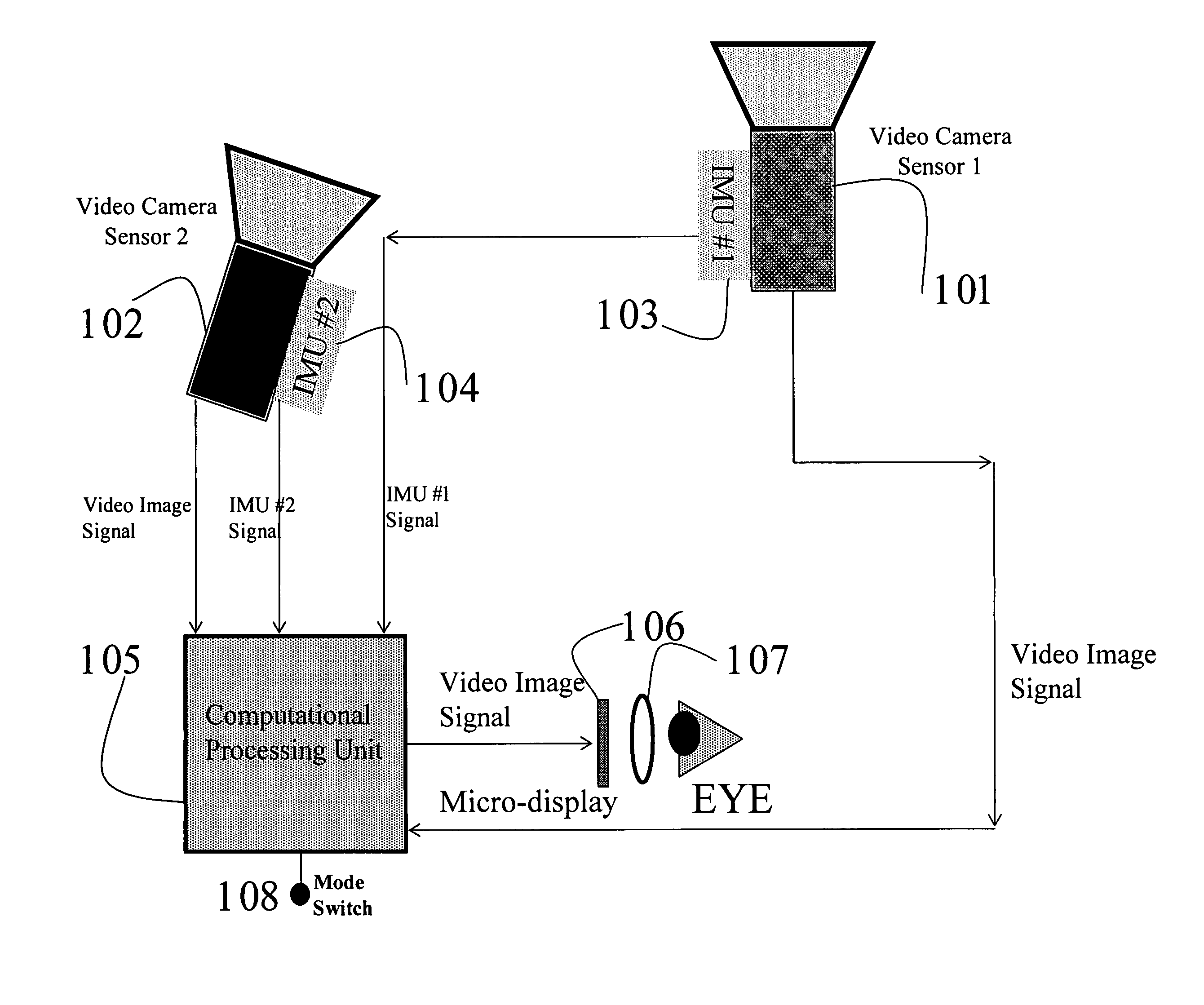
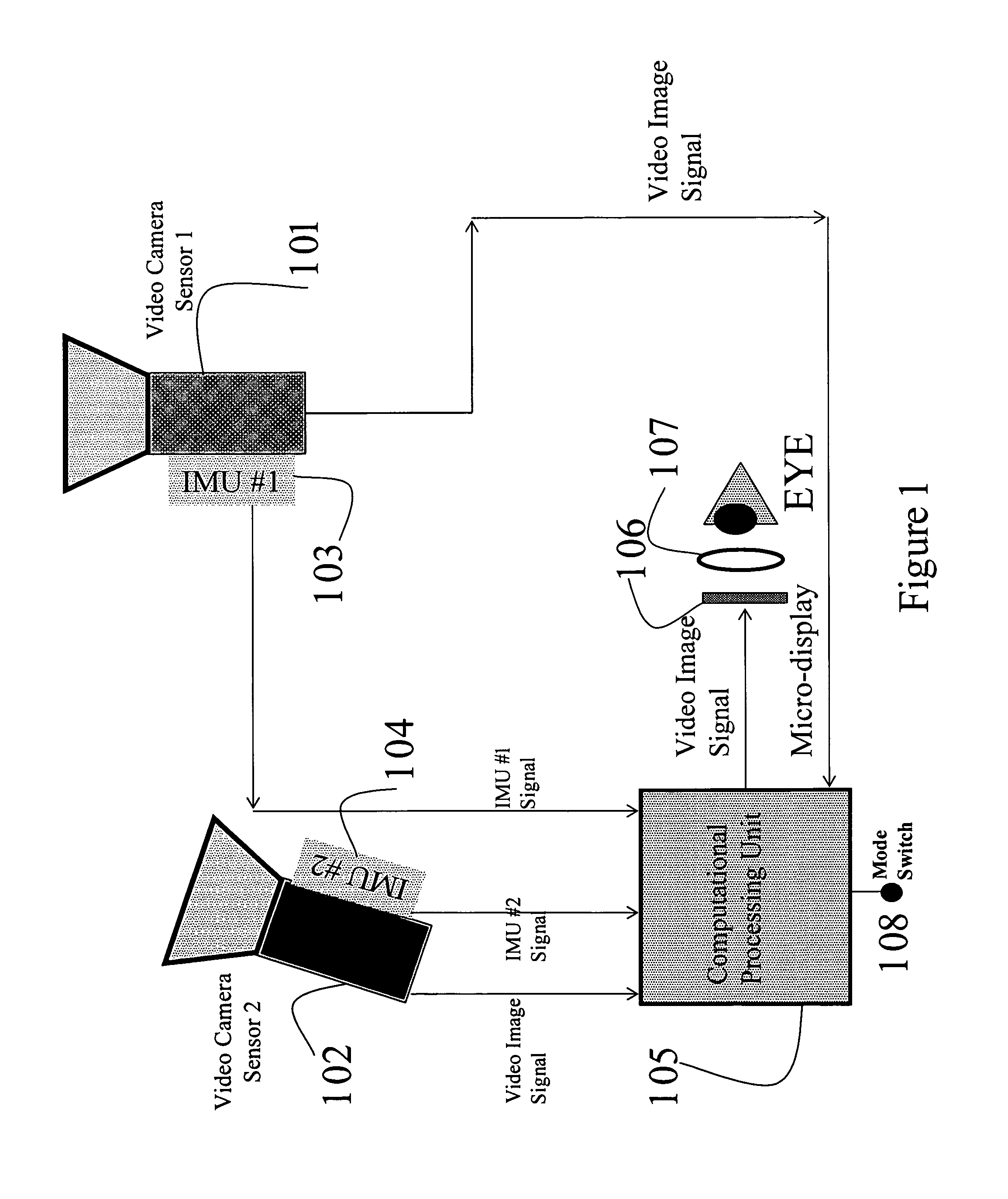
[0021]FIG. 1 shows a diagram consisting of two cameras 101 and 102, any one of which could be Visible, Intensified, VisNIR, SWIR, MWIR or an LWIR camera within proximity of each other but not necessarily collocated or boresighted. Camera 101 has rigidly attached Inertial Measurement Unit (IMU) (e.g., made by the companies Microstrain or InterSense) 103 and camera 102 has rigidly attached IMU 104 used to measure the relative orientation of the two cameras. Signals from IMUs 103 and 104 are passed to computational processing unit 105 that are related to the yaw, pitch and roll angular orientation of each IMU. Measurement of the relative orientation of IMUs 103 and 104 (and therefore cameras 101 and 102) is derived by the computational unit 105. This computational processing unit could be a general purpose PC, a Single Board Computer, an FPGA customized board or an ASIC, but is not limited to be one of these. In many cases the relative orientation measurement from IMUs 103 and 104 is n...


PUM


Abstract

A methodology and apparatus is described that registers images outputted by at least two video camera sensors that are not necessarily bore-sighted nor co-located together. Preferably this can be performed in real-time at least at video rate. The two video camera sensors can be either of similar or two different modalities (e.g., one can be intensified visible, while the other can be thermal infrared) each possibly with a different field-of-view. The methodology and apparatus take advantage of a combination of Inertial Measurement Units (IMUs) information and image registration between the two camera sensors from computational image processing. In one preferred embodiment, the system uses a rifle mounted weapon sight camera sensor and a helmet mounted sensor camera. The aim point of the weapon sight camera sensor (e.g., typically at the image center) zeroed to the true rifle aim point is digitally overlayed as a reticle on the video image from the helmet sensor, displayed on a head mounted display (HMD). In another embodiment pixel-level image fusion is displayed across the overlapping field-of-view of the rifle mounted camera sensor weapon sight with the helmet mounted camera image.

Description

CROSS REFERENCE TO RELATED APPLICATIONS[0001]This application claims the benefit, under 35 U.S.C. 119 (e), of U.S. Provisional Application No. 60 / 924,264, filed May 7, 2007 the disclosure of which is hereby incorporated herein by reference in its entirety.FIELD OF THE INVENTION[0002]The invention relates to the image co-registration and fusion of two video imaging sensors that are in proximity of each other but not necessarily co-located or bore-sighted.BACKGROUND OF THE INVENTION[0003]The ability to successfully operate in darkness is a cornerstone of our military superiority. This capability is supported by a number of sensor technologies that outfit the modern dismounted soldier. Ranging from intensified near infrared (NIR), through shortwave infrared (SWIR), midwave infrared (MWIR) and onto the longwave thermal infrared (LWIR), these technologies allow for unprecedented sensory enhancement and extended operational conditions. One negative aspect of the proliferation of night-vis...

Claims


Application Information

Patent Timeline
Patent Type & Authority Patents(United States)
IPC IPC(8): H04N7/18
CPCG02B27/017H04N5/23229H04N5/33G06T7/0028G06T7/0038H04N7/18G02B2027/0138G02B2027/014G06T2207/10021G06T2207/10048G06T2207/30212H04N5/272G06T7/33G06T7/38H04N23/63H04N23/90
Inventor SOCOLINSKY, DIEGO A.NEUHEISEL, JOSHUAWOLFF, LAWRENCE B.
Owner EQUINOX CORP
Why Eureka
Try Eureka