
Method for forming buffer layer in dye-sensitized solar cell

a solar cell and buffer layer technology, applied in the manufacture of final products, electrolytic capacitors, radio frequency controlled devices, etc., can solve the problems of reverse current and lower power generation efficiency, and achieve the effects of reducing the weight and cost of solar cells, reducing production equipment costs, and improving the electric characteristics of buffer layers and power generation efficiency

Inactive Publication Date: 2013-11-26
HITACHI ZOSEN CORP
View PDF9 Cites 0 Cited by
  • Summary
  • Abstract
  • Description
  • Claims
  • Application Information

AI Technical Summary

Benefits of technology

This method enables the instant sintering of the buffer layer without heating the entire electrode, reducing production costs and improving electric characteristics and power generation efficiency, while allowing for the use of lightweight synthetic resin substrates.

Problems solved by technology

Thus, a liquid electrolyte may cause leakage of electrons from the transparent electrode to the electrolyte layer, unfortunately leading to a reverse current and lower power generation efficiency.

Method used


Image

  • Method for forming buffer layer in dye-sensitized solar cell
  • Method for forming buffer layer in dye-sensitized solar cell
  • Method for forming buffer layer in dye-sensitized solar cell

Examples


first embodiment

[First Embodiment]

[0022]A method for forming a buffer layer in a dye-sensitized solar cell according to a first embodiment of the present invention will be described below with reference to the accompanying drawings.

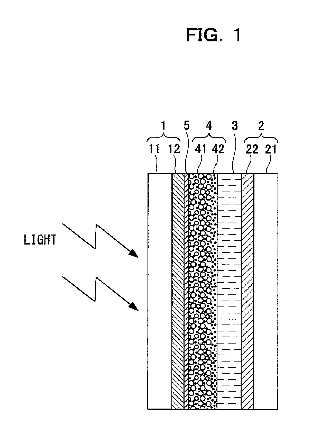
[0023]Referring to FIG. 1, the configuration of the dye-sensitized solar cell will be first schematically described below according to the first embodiment.

[0024]As illustrated in FIG. 1, the dye-sensitized solar cell includes a transparent electrode 1 serving as a negative electrode, a counter electrode 2 serving as a positive electrode, an electrolyte layer 3 disposed between the electrodes 1 and 2, and a photocatalyst film (also called a photocatalyst layer) 4 disposed between the electrodes 1 and 2 and near the transparent electrode 1. Moreover, a buffer layer 5 is interposed between the transparent electrode 1 and the photocatalyst film 4 to prevent a reverse electron flow. The buffer layer 5 is made of materials such as titanium oxide and zinc oxide and has a thick...

first example

[0045]A method for forming the buffer layer in the dye-sensitized solar cell will be discussed according to a first example, which will more specifically describe the first embodiment.

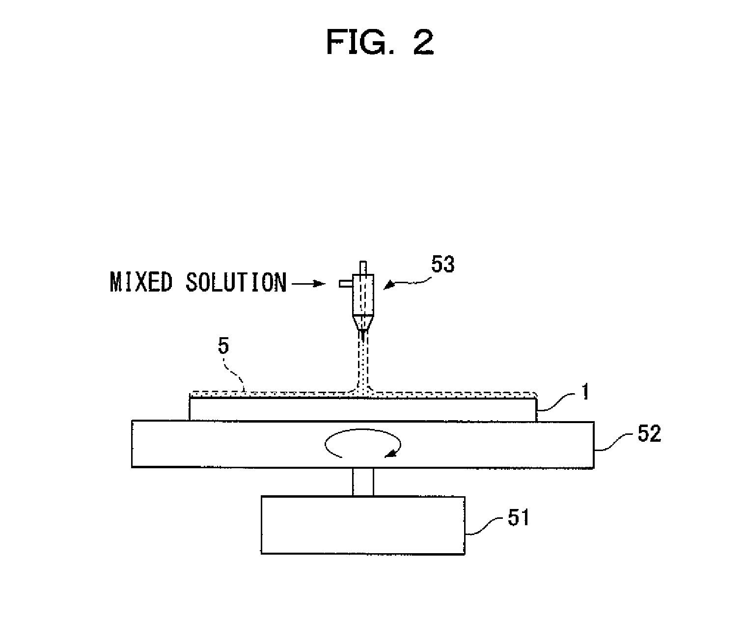
[0046]In the first example, first, a mixed solution of an alcohol solution and metal alkoxide was applied with a predetermined thickness on a commercial PEN-ITO film by spin coating.

[0047]The mixed solution to be applied (hereinafter, will be also called an applied solution) is obtained by dissolving 0.20 g of titanium (IV) isopropoxide (TTIP) in 37.50 g of propanol.

[0048]In the spin coating, an electrode was initially rotated at 500 rpm for five minutes and was finally rotated at 4000 rpm for 60 seconds. Thus, a coating having a thickness of about 5 nm was obtained. The coating was then sintered by laser beam irradiation to obtain the buffer layer.

[0049]The materials of the applied solution are not limited. For example, titanium tetraethoxide, titanium tetrachloride, and titanium hydroxide are usable....

second example

[0056]A method for forming the buffer layer in the dye-sensitized solar cell according to a second example will be described below.

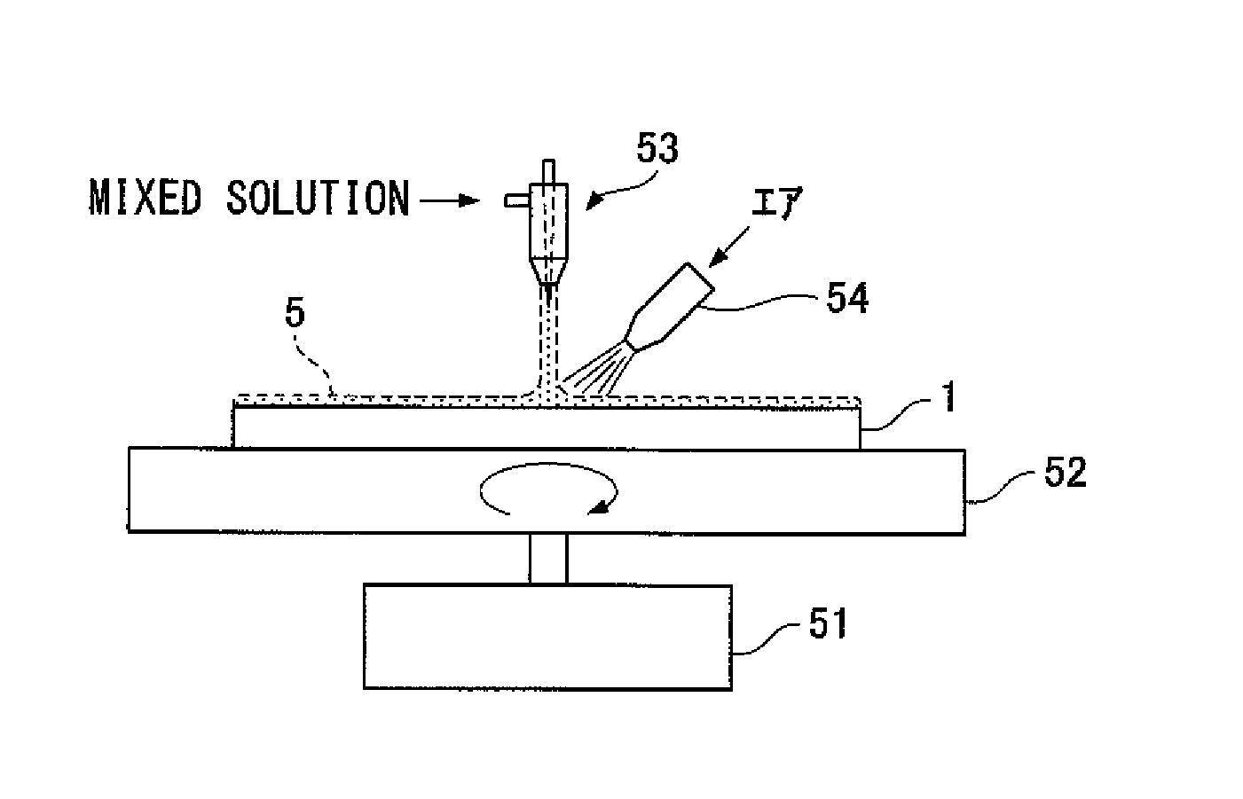
[0057]The buffer layer of the second example is formed by spin coating as in the first example. As illustrated in FIG. 4, air is blown as gas to the surface of the transparent electrode 1 from a gas supply nozzle 54. Specifically, blowing air moves sequentially from the center of rotation to the outer edge of the transparent electrode 1. The blowing air can prevent an applied solution from being retained around the transparent electrode 1. Moreover, even in the case where the transparent electrode has a rough surface (particularly, a synthetic resin plate), a mixed solution can be thinly and evenly applied, achieving a small and even thickness over the buffer layer 5. The gas is not limited to air as long as the gas does not react with the mixed solution to be applied.

[0058]The applied film may be then irradiated with a laser beam to sinter metal alkoxid...


PUM


Abstract

A method for forming a buffer layer in a dye-sensitized solar cell including a transparent electrode, a counter electrode, an electrolyte layer disposed between the electrodes, and a photocatalyst film disposed between the electrodes and near the transparent electrode, the buffer layer being disposed between the transparent electrode and photocatalyst film, the method including: forming the buffer layer by sintering a mixed solution of an alcohol solution and 0.03% to 5% by mass of metal alkoxide by laser beam irradiation after applying the mixed solution to the surface of the transparent electrode by spin coating, the transparent electrode being rotated by a rotating table.

Description

TECHNICAL FIELD[0001]The present invention relates to a method for forming a buffer layer in a dye-sensitized solar cell.BACKGROUND ART[0002]Generally, a dye-sensitized solar cell includes: a transparent electrode including a transparent conductive film formed on a transparent substrate, e.g., a glass plate; a counter electrode including a similar transparent conductive film formed on the surface of a transparent substrate; an iodized electrolyte layer disposed between the electrodes; and a photocatalyst film disposed between the electrodes and on the surface of the transparent electrode. A known photocatalyst film contains a metallic oxide such as titanium oxide (TiO2) and is stained with a photosensitizing dye such as ruthenium.[0003]With this configuration, the transparent electrode and the electrolyte layer are in contact with each other. Thus, a liquid electrolyte may cause leakage of electrons from the transparent electrode to the electrolyte layer, unfortunately leading to a ...

Claims


Application Information

Patent Timeline
Patent Type & Authority Patents(United States)
IPC IPC(8): H01L21/00
CPCH01G9/2031H01G9/2059Y02E10/542H01L51/0027Y02P70/50H10K71/421H01L31/04H01L31/0216H01L31/18
Inventor SUGIYO, TAKESHIINOUE, TETSUYA
Owner HITACHI ZOSEN CORP
Learn More