Encapsulated ballistic protection system

a ballistic protection and ballistic technology, applied in the field of ballistic protection systems, can solve the problems of reducing affecting reducing the safety of personnel, so as to enhance the overall ballistic performance capability, enhance the ballistic resistance performance, and improve the overall ballistic performance. the effect of performan

Inactive Publication Date: 2013-12-31
KELLY SPACE & TECH
View PDF12 Cites 7 Cited by
  • Summary
  • Abstract
  • Description
  • Claims
  • Application Information

AI Technical Summary

Benefits of technology

[0027]Aspects of embodiments of the present invention are directed to an encapsulated ballistic protection system (EBPS) that combines advantages of dense armor material compositions with the ballistic retention, reflection, and energy dissipation characteristics of fibrous materials, and which may further embody some of the behavioral characteristics of Reactive Armor. Further aspects of embodiments of an EBPS according to the present invention incorporate characteristics of the encapsulation material that enables it to serve as a structural retention layer to constrain the encapsulated ballistic protection material in order to reduce expansion beyond the boundaries of the encapsulation layer, which enhances the overall ballistic performance capability. Additional aspects of embodiments of the present invention include a unique encapsulated and layered component configuration adapted for providing significantly enhanced ballistic resistance performance, weight advantage, and reduction in backface signature over typical armor solutions.
[0028]Embodiments of an EBPS according to the present invention can be easily tailored to meet virtually any application and / or threat level. Further, embodiments of an EBPS according to the present invention are adapted to disburse projectile impact loads over large surface areas, resulting in lower impact loads on the protected surface and reduced backface signature. Further, embodiments of an EBPS according to the present invention enable the integration of structure and armor to create “structural armor” and can be formed and / or molded into virtually any shape or configuration to ensure complete armor coverage with enhanced mobility and flexibility for ease of movement. Additional aspects of embodiments of an EBPS according to the present invention are ease of incorporation of flammability and smoke resistance in accordance with ASTM E84, as well as decreased thickness compared to typical equivalently performing armor configurations. Additionally, embodiments of an EBPS according to the present invention enable the incorporation of one or more sensor systems to detect, measure, assess, and / or report impact loads on the EBPS, integrity breach to the EBPS, and / or a physical location of the EBPS.
[0030]In one embodiment, the one or more ballistic protection material layers are substantially encapsulated by the encapsulation material on a first side adapted to face the human or the object and on a second side opposite the first side and adapted to face the projectile, and the EBPS further includes a compressible layer between the one or more ballistic protection material layers and the encapsulation material on the first side, the compressible layer configured to at least one of dissipate energy, reduce velocity of the projectile, and reduce backface deformation. The compressible layer may include at least one material selected from the group consisting of hard board foams, honeycomb materials, and rubber compounds.
[0034]In one embodiment, the first encapsulation layer includes a first foam member configured to at least one of dissipate energy, reduce velocity of the projectile, and reduce backface deformation. In one embodiment, the fragmentation resistance layer is deformable against at least one of the compressible layer and the first foam member for at least one of dissipating energy, reducing velocity of the projectile, and reducing backface deformation. In one embodiment, the first encapsulation layer further includes a first thermal barrier between the first foam member and the one or more ballistic protection material layers, and a first outer skin on a side of the first foam member opposite the first thermal barrier. In one embodiment, the second encapsulation layer includes a second foam member, a second thermal barrier between the second foam layer and the one or more ballistic protection material layers, and a second outer skin on a side of the second foam member opposite the second thermal barrier.
[0043]In one embodiment, an EBPS further includes a compressible layer between the first encapsulation layer and the ballistic protection material layer and configured to at least one of dissipate energy, reduce velocity of the projectile, and reduce backface deformation.

Problems solved by technology

During World War I, the United States developed several types of body armor, including a chrome nickel steel breastplate and a headpiece that could withstand Lewis Gun bullets at 2,700 feet per second, but was clumsy and heavy at 40 pounds.
In the early stages of World War II, the United States designed body armor for infantrymen, but most models were heavy and significantly restricted mobility.
Additionally, these armor vests were often incompatible with existing equipment.
These flak jackets were made of nylon fabric and capable of stopping flak and shrapnel, but not designed to stop bullets.
During the Korean War, several new vests were produced for the United States military, which made use of fiberglass or aluminum segments woven into a nylon vest, although these vests were not considered very effective.
Since the 1970s, several new fibers and construction methods for bulletproof fabric have been developed besides woven KEVLAR, such as DSM's DYNEEMA, Honeywell's GOLD FLEX and SPECTRA, Teijin's TWARON, Pinnacle Armor's DRAGON SKIN, and Toyobo's ZYLON (now controversial, as new studies report that it degrades rapidly, leaving wearers with significantly less protection than expected).
Even without penetration, modern pistol bullets contain enough energy to cause blunt force trauma under the impact point.
Vests designed for bullets offer little protection against stabbing knife blows, arrows, ice picks, and bullets manufactured of non-deformable materials (i.e. steel core instead of lead).
The weight and stiffness of rifle armor is a major technical challenge.
While ceramic materials have some outstanding properties for ballistics, they are not strong under tensile loads.
For these applications, heavy armor panels are applied parasitically, in that they are externally applied to the surface area to be protected.
These heavy armor applications possess the key disadvantage of significant added weight, and can also create additional collateral damage if penetrated and compromised by becoming projectiles themselves.
On attack by a penetrating weapon, the explosive detonates, forcibly driving the metal plates apart to damage the penetrator.
The backface signature allowed by different test standards can be difficult to compare.
However, in general, the U.K., German, and other European standards allow 20-25 mm of backface signature while the U.S.-NIJ standards allow for 44 mm, which can potentially cause internal injury.
The allowable backface signature for body armor has been controversial since its introduction in the first NIJ test standard, and the debate as to the relative importance of penetration-resistance versus backface signature continues in the medical and testing communities.
In general, a vest's textile material temporarily degrades when wet.
Some existing armor systems encase the armor solution using methods ranging from simply applying coatings as a vapor barrier to fiberglass wrapping to serve as environmental protection and abrasion resistance, but not for the express purpose of enhancing the structural integrity of the armor system.

Method used


Image

  • Encapsulated ballistic protection system
  • Encapsulated ballistic protection system
  • Encapsulated ballistic protection system

Examples


Embodiment Construction

[0054]In the following detailed description, certain exemplary embodiments of the present invention are shown and described, by way of exemplary embodiments. As those skilled in the art would recognize, the described exemplary embodiments may be modified in various ways without departing from the spirit and scope of the present invention. Accordingly, the drawings and description are to be regarded as illustrative in nature, rather than restrictive.

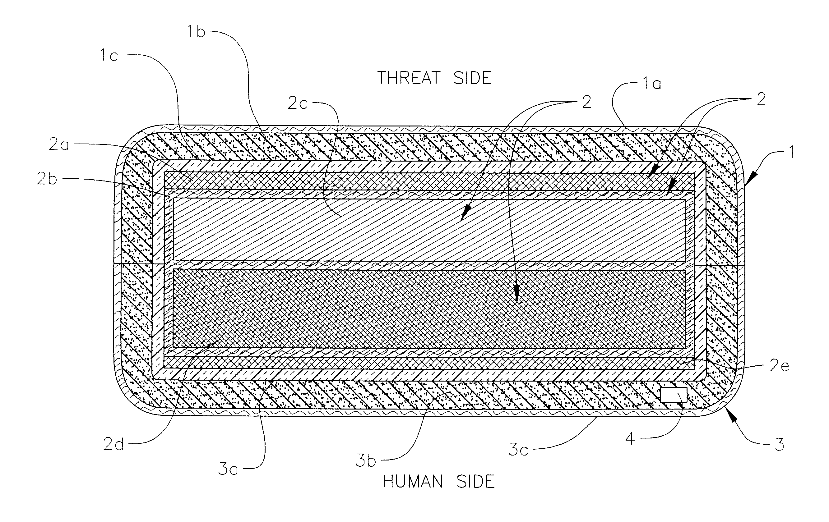
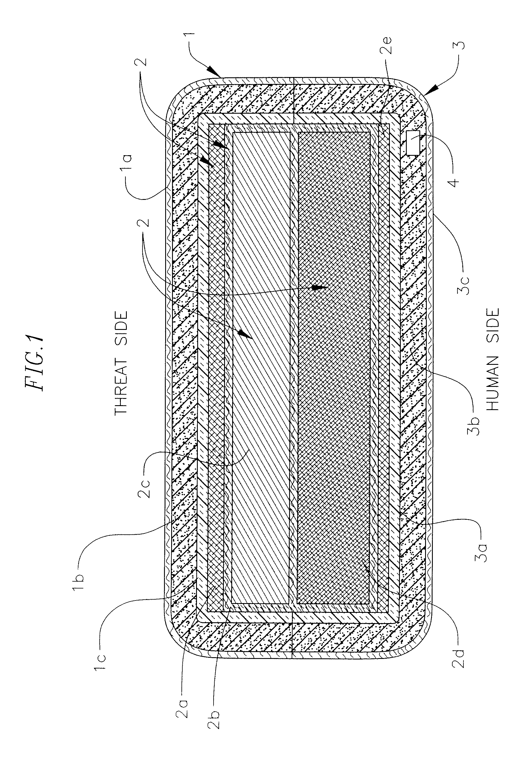
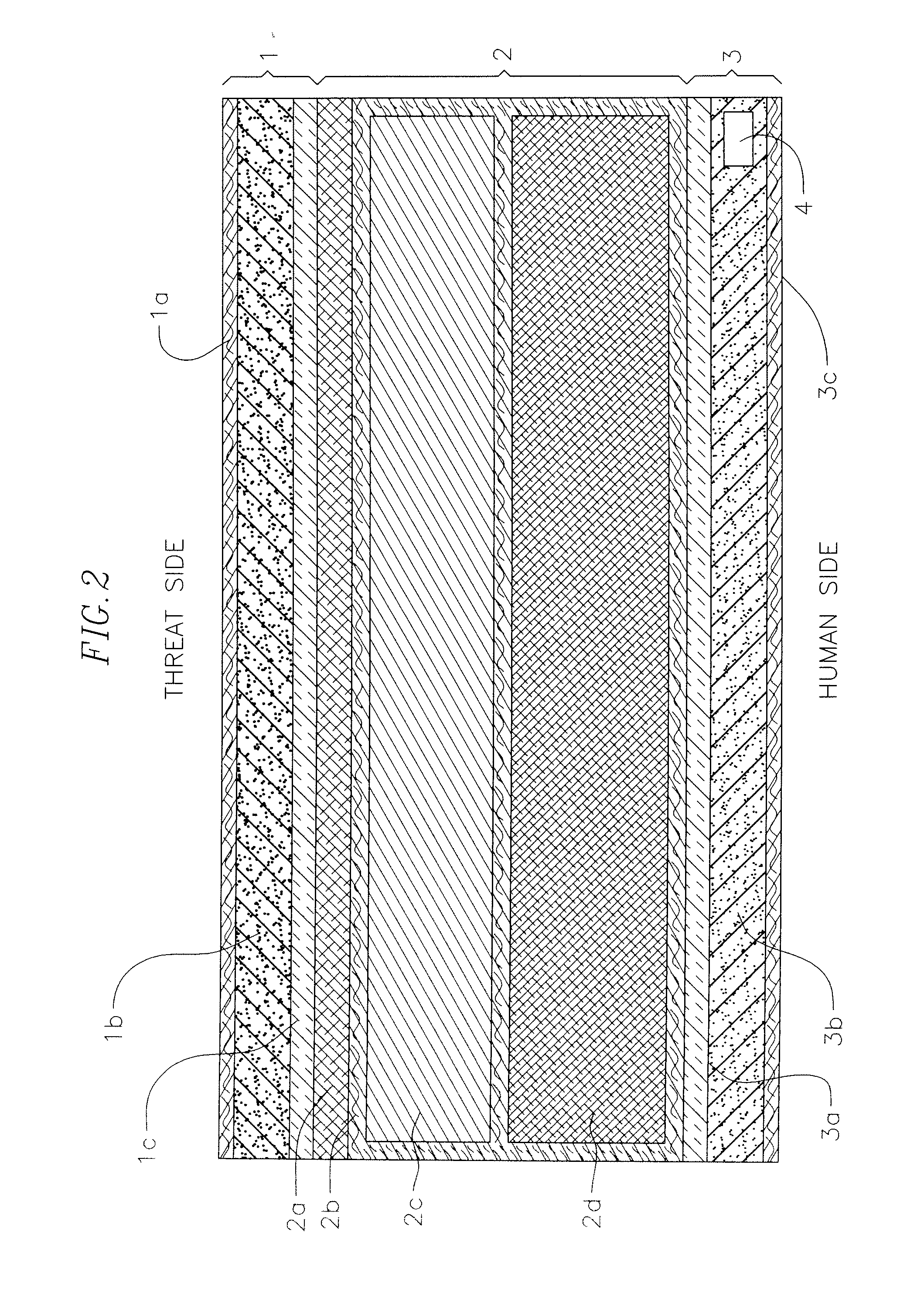
[0055]As used herein with respect to embodiments of the present invention, the term “encapsulated” refers to the complete covering of all surfaces of an object, material, or group of materials by one or more “encapsulating” or “encapsulation” materials and / or layers.

[0056]Embodiments of an encapsulated ballistic protection system (EBPS) according to the present invention include a layered system defining a panel or structure composed of a variety of materials arranged in an order to provide ballistic resistance and protection. In some emb...


PUM

PropertyMeasurementUnit
tensile strengthaaaaaaaaaa
speedsaaaaaaaaaa
thickaaaaaaaaaa

Abstract

An encapsulated ballistic protection system (EBPS). In one embodiment, an EBPS for protecting a human or an object from a projectile includes one or more ballistic protection material layers at least substantially encapsulated by encapsulation material having a tensile strength of 20,000 psi or greater. Additionally, in one embodiment, an EBPS includes one or more ballistic protection material layers that are substantially encapsulated by the encapsulation material on a first side adapted to face the human or the object and on a second side opposite the first side and adapted to face the projectile, and the EBPS further includes a compressible layer between the one or more ballistic protection material layers and the encapsulation material on the first side, the compressible layer configured to at least one of dissipate energy, reduce velocity of the projectile, and reduce backface deformation.

Description

CROSS-REFERENCE TO RELATED APPLICATIONS[0001]This application claims priority to and the benefit of each of U.S. Provisional Application No. 61 / 090,196, filed on Aug. 19, 2008, and U.S. Provisional Application No. 61 / 095,908, filed on Sep. 10, 2008, the entire content of each of which is incorporated herein by reference.FIELD OF THE INVENTION[0002]The present invention relates generally to ballistic protection systems, and more particularly to an encapsulated ballistic protection system.BACKGROUND[0003]Firearm ballistic resistive armor dates back to the late 1500s and consisted of metallic armor that was malleable enough to dissipate energy without allowing penetration. The first “soft” ballistic armor known was invented in Korea in the 1860s, which was formed into vests made of 30 folds of cotton. During the early 1880s, silk vests resembling medieval padded jackets were used that consisted of 18 to 30 layers of cloth to stop the relatively slow rounds from black powder handguns.[0...

Claims


Application Information

Patent Timeline
Patent Type & Authority Patents(United States)
IPC IPC(8): F41H5/04
CPCF41H5/0428F41H5/04F41A17/06
Inventor GALLO, MICHAEL J.BURLEY, WILLIAM
Owner KELLY SPACE & TECH
Why Eureka
Try Eureka