Systems and methods for generating in-situ carbon dioxide driver gas for use in enhanced oil recovery

a technology of driver gas and carbon dioxide, which is applied in the field of system and method for generating in-situ co2, can solve the problems of difficult and costly construction of cosub>2 /sub>pipelines, hampered use of cosub>2 /sub>pipelines, and inability to construct cosub>2 /sub>pipelines, etc., to achieve enhanced oil recovery, enhance oil recovery, and enhance oil recovery

Inactive Publication Date: 2013-12-31
PIONEER ENERGY
View PDF135 Cites 84 Cited by
  • Summary
  • Abstract
  • Description
  • Claims
  • Application Information

AI Technical Summary

Problems solved by technology

The U.S. oil industry, as the leader in enhanced oil recovery technology, faces the challenge of further molding this technology towards economically producing these more costly remaining domestic oil resources.
There are tens of thousands of depleted oil and natural gas wells around the world, which collectively possess significant amounts of petroleum resources that cannot currently be extracted using conventional extraction techniques.
Despite the potential advantages of CO2 in enhanced recovery, its use has been hampered by several factors.
Unfortunately, such CO2 pipelines are difficult and costly to construct.
For most oil fields, a CO2 pipeline is not a viable option because of a mix of several problems: (a) The capital investment for building a pipeline—sometimes tens or hundreds of millions of dollars; (b) The time-frame of building a pipeline—several years; (c) The distance and terrain issues between the source and destination which either makes the pipeline impossible or simply not economical; (d) The time it takes to obtain easement rights and permits is long; and (e) The time it takes to start generating an increase in productivity—the return on investment (ROI) is too long.
However, the project cost hundreds of millions of dollars, and took over 5 years of planning, permitting, and construction to complete.
Therefore, when faced with the hurdles and overall costs of the pipeline-delivered CO2, as described above, tertiary CO2 EOR simply does not make economical sense for most oil fields, especially small producers scattered all over the United States and the world.
For many reasons, including notably those laid out above, as well as the fact that flue gases from conventional fossil power plants typically contain relatively low (2 concentrations, such stations offer little potential utility for supporting EOR, especially by small producers.
Moreover, traditionally, hydrogen has been costly to produce and its use has not been justified from an economic standpoint.

Method used


Image

  • Systems and methods for generating in-situ carbon dioxide driver gas for use in enhanced oil recovery
  • Systems and methods for generating in-situ carbon dioxide driver gas for use in enhanced oil recovery
  • Systems and methods for generating in-situ carbon dioxide driver gas for use in enhanced oil recovery

Examples


embodiment 600

[0124]In an alternative embodiment 600, depicted in FIG. 6, a fluidized-bed reformer 601 is used to generate high pressure gas. In the fluidized-bed reformer 601, most particles remain in the reaction chamber, but finer particles are entrained with the exhaust gas. That is, compared to the fixed-bed reformer 501 of FIG. 5, greater amounts of fine particles are entrained in the higher velocity exhaust gas (relative to the exhaust gas generated in the fixed-bed reformer) and must be removed prior to compression of the driver gas. The coarsest of the entrained particles are removed from the gas stream and can be recycled to the reformer or discharged as residue. The remaining finest particles are removed by filtration.

[0125]FIG. 6 illustrates an example of an embodiment of a system utilizing the fluidized-bed reformer 601. Delivered carbonaceous fuel 602 with a feed particle size of approximately less than ¼-inch is introduced into hopper 603. The carbonaceous fuel is fed into fluidize...

embodiment 1100

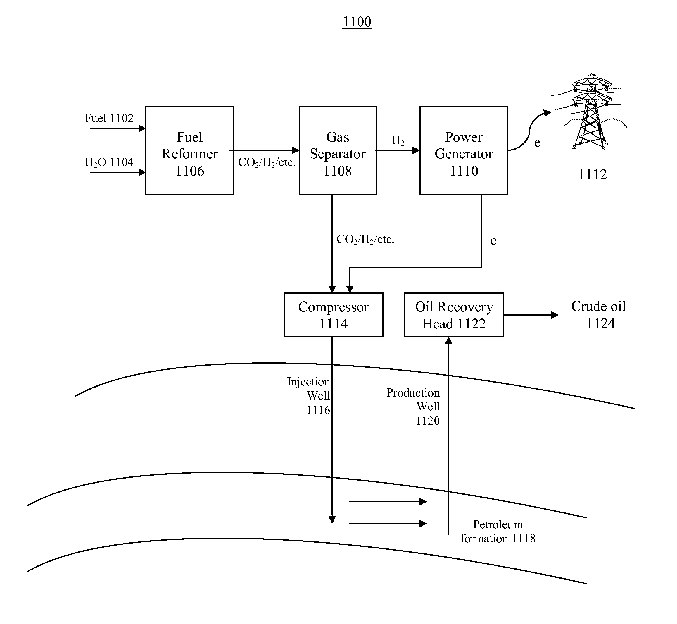
[0175]FIG. 11 illustrates another example of an embodiment 1100 of the present invention for extracting oil from an oil site and for generating electricity. This example is illustrative only, and is not intended to limit the scope of the present invention. Fuel 1102 and water 1104 are fed into reformer module 1106. The fuel and water may also be pre-mixed and fed into reformer 1106 as a single stream. Oxygen, or another oxidizing agent, may be added to reformer 1106 via another line (not shown), or pre-mixed with either the fuel, or water, or both. Generated driver gas, which may include CO2, H2, as well as other gases, is fed into gas separator 1108, which separates a portion of the hydrogen gas from the other driver gases. A portion of the separated hydrogen gas is fed into power generator 1110, which could be a gas turbine, to generate electricity. A portion of the electricity is fed into the electric grid 1112. A portion of the electricity may also be used on-site, to provide po...


PUM


Abstract

The present invention is an in-situ apparatus for generating carbon dioxide gas at an oil site for use in enhanced oil recovery (EOR). The apparatus includes a steam generator adapted to boil and superheat water to generate a source of superheated steam, as well as a source of essentially pure oxygen. The apparatus also includes a steam reformer adapted to react a carbonaceous material with the superheated steam and the pure oxygen, in an absence of air, to generate a driver gas comprising primarily carbon dioxide gas and hydrogen gas. A separator is adapted to separate at least a portion of the carbon dioxide gas from the rest of the driver gas to generate a carbon dioxide-rich driver gas and a hydrogen-rich fuel gas. A compressor is used for compressing the carbon dioxide-rich driver gas for use in enhanced oil recovery, and the compressed carbon dioxide-rich driver gas, with substantially no oxygen, is injected to a predetermined depth in order to enhance oil recovery at the oil site. Unlike traditional CO2-EOR, which requires large power plants stationed near metropolitan areas and expensive pipeline networks, the in-situ apparatus can be placed or constructed at the site of the oil field, while a portion of the carbonaceous material may be obtained from a site outside the oil field.

Description

CROSS-REFERENCE TO RELATED APPLICATIONS[0001]This application is a Continuation-in-Part (CIP) and claims priority from U.S. Ser. No. 12 / 165,585, entitled “SYSTEMS FOR EXTRACTING FLUIDS FROM THE EARTH AND FOR GENERATING ELECTRICITY WITHOUT GREENHOUSE GAS EMISSIONS,” filed on Jun. 30, 2008, now U.S. Pat. No. 7,810,565, which itself is a Continuation of U.S. Ser. No. 11 / 751,028, entitled “PORTABLE AND MODULAR SYSTEM FOR EXTRACTING PETROLEUM AND GENERATING POWER,” filed on May 20, 2007, and issued on Jan. 26, 2010, as U.S. Pat. No. 7,650,939. The entirety of both patents is hereby incorporated by reference herein.FIELD OF THE INVENTION[0002]This invention relates to a system and method for generating in-situ CO2 from a carbonaceous feedstock for use in enhanced oil recovery. One embodiment of the present invention is a power plant which utilizes a steam reforming process that may be used to generate electricity, hydrogen, and high pressure carbon dioxide-rich gas which is utilized for E...

Claims


Application Information

Patent Timeline
Patent Type & Authority Patents(United States)
IPC IPC(8): E21B43/40
CPCE21B43/168Y02C10/14E21B43/164Y02C20/40Y02P90/70
Inventor ZUBRIN, ROBERT M.BERGGREN, MARK H.
Owner PIONEER ENERGY
Why Eureka
Try Eureka