System and method for four dimensional angiography and fluoroscopy

a four-dimensional angiography and fluoroscopy technology, applied in the field of angiography, can solve the problems of significant incidence of serious complications, inability to eliminate, and limited post-processing of images, and achieve the effect of removing the effects of time-dependent vascular behavior

Active Publication Date: 2014-02-18
CMS MEDICAL +1
View PDF35 Cites 17 Cited by
  • Summary
  • Abstract
  • Description
  • Claims
  • Application Information

AI Technical Summary

Benefits of technology

[0013]Yet another embodiment of the present invention includes a partial filtered back projection reconstruction employing one or more segments of angles which provide a weighting image that is multiplied into the static 3D rotational vascular data set. This provides a better approximation to the time-dependent perfusion of the intravascular tissue. For single source / single detector systems, the filtered back projection is generated with a single angular segment composed of several adjacent projections. For bi-plane systems, two segments separated by approximately 90 degrees can be employed. To remove the effects of time-dependent vascular behavior, vessels can be segmented out before multiplication of the tissue component of the projections and the tissue component of the static 3D data set.

Problems solved by technology

For decades, post-processing of images was largely limited to the use of film subtraction techniques.
These practices were associated with a significant incidence of serious complications.
The development of percutaneous techniques allowing the use of a single catheter to study multiple arterial segments reduced, but this by no means eliminated, these adverse events.
However, it quickly became apparent that the IV-DSA technique was limited by problems due to suboptimal viewing angles and vessel overlap that could only be reduced by repeated injections.
Even then, these factors were problematic unless a projection that avoided the overlap of relevant vascular structures could be defined.
Similar problems occurred when using biplane acquisitions.
Current limitations in the temporal resolution capabilities of x-ray angiographic equipment require that rotational acquisitions be obtained over a minimum time of about 5 seconds.
This limitation is a significant factor in making it prohibitively difficult to accurately measure the dimensions of both normal and abnormal vascular structures.
Current DSA-based techniques do not depict the temporal sequence of filling in a reconstructed 3D-DSA volume.
CTA provides high spatial resolution, but it is not time-resolved unless the imaging volume is severely limited.
CTA is also limited as a standalone diagnostic modality by artifacts caused by bone at the skull base and the contamination of arterial images with opacified venous structures.
Further, CTA provides no functionality for guiding or monitoring minimally-invasive endovascular interventions.
Nonetheless, the spatial and temporal resolution of MRA are not adequate for all imaging situations and its costs are considerable.
With traditional DSA it is difficult or impossible to image and display these structures without the overlap of adjacent vessels.
This problem is compounded when visualizing abnormal structures with complex geometry, such as aneurysms, or when abnormally fast or slow flow is present, such as in vascular malformations or ischemic strokes.
Not only does this use large amounts of contrast medium, but the risk of thromboembolic complications increases with each injection.

Method used


Image

  • System and method for four dimensional angiography and fluoroscopy
  • System and method for four dimensional angiography and fluoroscopy
  • System and method for four dimensional angiography and fluoroscopy

Examples


Embodiment Construction

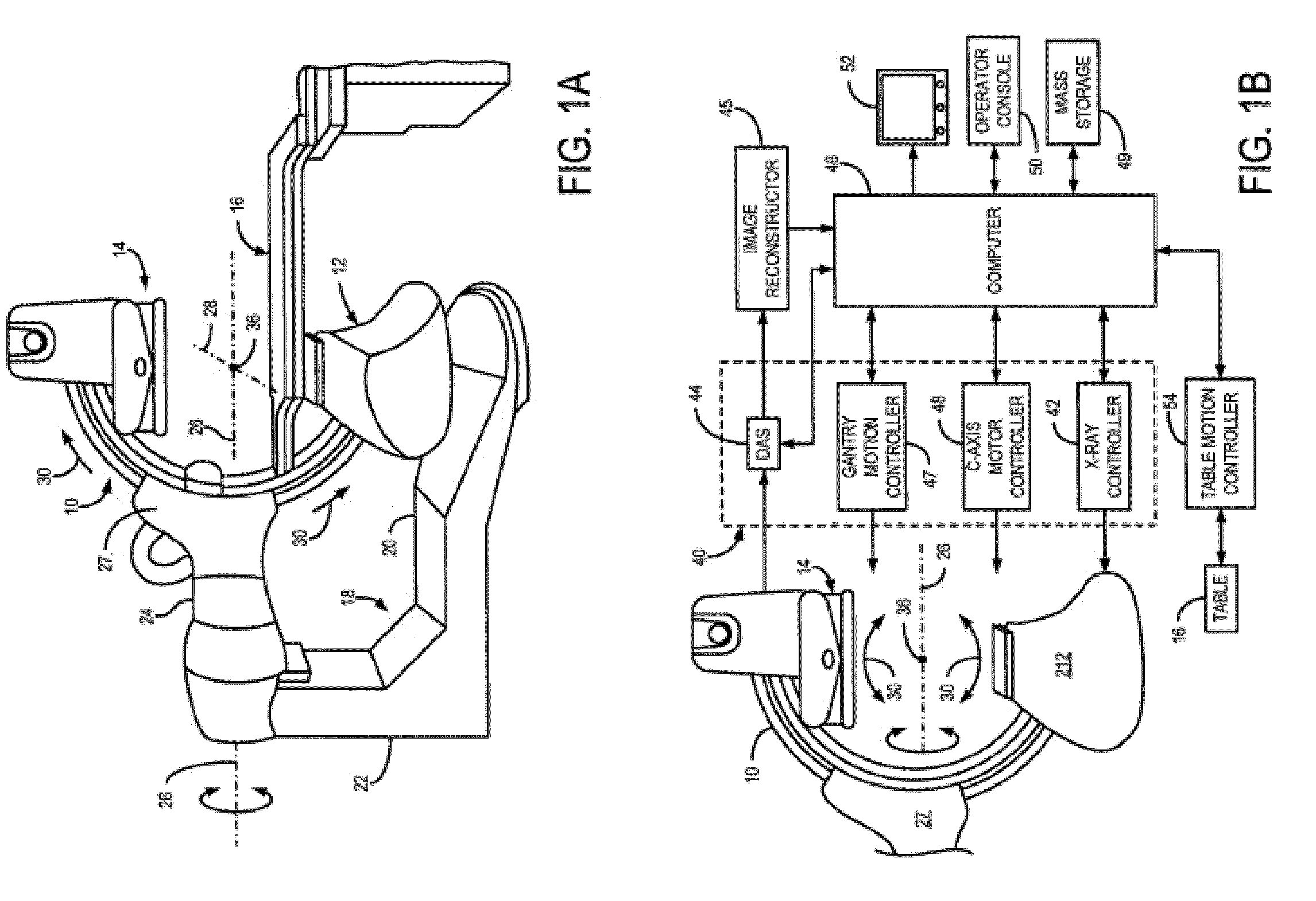
[0028]Referring to FIG. 1A, the present invention may employ a rotational x-ray system that is designed specifically for use in connection with interventional procedures. It is characterized by a gantry having a C-arm 10 which carries an x-ray source assembly 12 on one of its ends and an x-ray detector array assembly 14 at its other end. The gantry enables the x-ray source 12 and detector 14 to be oriented in different positions and angles around a patient disposed on a table 16, while enabling a physician access to the patient.

[0029]The gantry includes an L-shaped pedestal 18 which has a horizontal leg 20 that extends beneath the table 16 and a vertical leg 22 that extends upward at the end of the horizontal leg 20 that is spaced from of the table 16. A support arm 24 is rotatably fastened to the upper end of vertical leg 22 for rotation about a horizontal pivot axis 26.

[0030]The pivot axis 26 is aligned with the centerline of the table 16, and the arm 24 extends radially outward f...


PUM


Abstract

A method for generating time-resolved 3D medical images of a subject by imparting temporal information from a time-series of 2D medical images into 3D images of the subject. Generally speaking, this is achieved by acquiring image data using a medical imaging system, generating a time-series of 2D images of a ROI from at least a portion of the acquired image data, reconstructing a 3D image substantially without temporal resolution from the acquired image data, and selectively combining the time series of 2D images with the 3D image. Selective combination typically involves registering frames of the time-series of 2D images with the 3D image, projecting pixel values from the 2D image frames “into” the 3D image, and weighting the 3D image with the projected pixel values for each frame of the time-series of 2D images. This method is particularly useful for generating 4D-DSA images (that is, time-resolved 3D-DSA images) from a time-series of 2D-DSA images acquired via single plane or biplane x-ray acquisitions with 3D images acquired via a rotational DSA acquisition. 4D-DSA images can be generated either by using multiple injections or by using a single injection by combining a time-series of 2D-DSA images generated from individual projections from a rotational x-ray acquisition with a 3D image reconstructed from substantially all of the projection views acquired during the rotational x-ray acquisition. These DSA images may have a spatial resolution on the order of 5123 pixels and a temporal resolution of about 30 frames per second, which represents an increase over traditional 3D-DSA frame rates by a factor of between 150 and 600.

Description

CROSS-REFERENCE TO RELATED APPLICATIONS[0001]This application is a continuation-in-part of U.S. patent application Ser. No. 12 / 542,376 titled SYSTEM AND METHOD OF TIME-RESOLVED, THREE-DIMENSIONAL ANGIOGRAPHY filed Aug. 17, 2009, which is hereby incorporated by reference in its entirety herein.BACKGROUND OF THE INVENTION[0002]The present invention relates to angiography and, more particularly, to a system and method for producing time-resolved, three-dimensional (thus, resulting in four dimensional) angiographic and fluoroscopic images.[0003]Since the introduction of angiography beginning with the direct carotid artery punctures of Moniz in 1927, there have been ongoing attempts to develop angiographic techniques that provide diagnostic images of the vasculature, while simultaneously reducing the invasiveness associated with the procedure. For decades, post-processing of images was largely limited to the use of film subtraction techniques. Initial angiographic techniques involved dir...

Claims


Application Information

Patent Timeline
Patent Type & Authority Patents(United States)
IPC IPC(8): G06T15/00H05G1/60A61B6/00
CPCA61B6/481A61B6/4441A61B6/486A61B6/5247A61B6/487G06T11/008G06T2211/436A61B6/12A61M5/007A61B6/5223Y10S378/901A61B6/02A61B6/504A61B6/485G06T2211/412G06T2211/404A61B6/022
Inventor MISTRETTA, CHARLES A.STROTHER, CHARLES M.
Owner CMS MEDICAL
Why Eureka
Try Eureka