Method for fabricating composite grid-stiffened structures with integrated fluid channels

a fluid channel and composite grid technology, applied in the field of thermal management systems, can solve the problems of limiting the amount of heat which can be dissipated and rejected using this approach, limiting the placement of electronic components within the spacecraft, and difficult to efficiently transfer heat over large distances, etc., to achieve the effect of improving the physical properties of the structural tissue, promoting self-healing, and large fluid flow ra

Active Publication Date: 2014-02-25
THE UNITED STATES OF AMERICA AS REPRESETNED BY THE SEC OF THE AIR FORCE
View PDF17 Cites 10 Cited by
  • Summary
  • Abstract
  • Description
  • Claims
  • Application Information

AI Technical Summary

Benefits of technology

[0007]The multifunctional nature of the panel was inspired by the circulatory system of biological organisms, which maintains temperature, distributes oxygen, promotes self-healing, and improves the physical properties of structural tissue. The geometry of a conventional structural panel is modified by incorporating supply channels into the ribs of the panel. These supply channels feed smaller distribution channels embedded in the panel face sheet. The supply channels are analogous to the arteries in a circulatory system, providing relatively large fluid flow rates at low pressure drop. The channels embedded in the face sheet are analogous to capillaries, providing a large surface area through which heat transfer may occur. A network of pumps and valves are used to control the flow rate and flow path of the fluid, similar to the heart and valves found in many living organisms.
[0008]A novel method of fabricating such a panel is disclosed in which layers of uncured composite prepreg (prepreg is a term for “pre-impregnated” composite fibers) are draped over a plurality of expansion tooling blocks. Plugs, which act to seal gaps in the channels and may serve as mounting surfaces for pumps and valves, may be placed among the prepreg / expansion tooling assembly where required. The prepreg, plug, and expansion tooling block assembly are placed inside a base tooling assembly, which is comprised of a material with low or predictable thermal stability. The draping of the prepreg over the individual expansion tooling blocks and the subsequent assembly of these blocks is unique to the disclosed fabrication process and a key step in producing the desired final product. The entire assembly is either bagged or enclosed with a cover plate and autoclaved to cure the prepreg and bond the plugs. A face sheet with embedded channels is then placed on top of the cured structure and used to seal the integrated channels which result from the previously described process. The face sheet may consist of a plurality of prepreg layers, the inner layers of which may be machined to contain the desired distribution channel geometry. In this embodiment, the outer layers act to seal these embedded channels, with inlet and outlet openings machined where desired so that flow may pass between the distribution and supply channels. In an alternative embodiment, fluid channels may be machined in the top portion of the structural ribs. The result of this novel fabrication process is a low-mass, high-stiffness structural panel with integrated fluid passageways that may provide improved thermal performance over existing thermal management systems by providing a variable and increased effective thermal conductivity of the panel and heat removal rate from the panel.

Problems solved by technology

Unfortunately, the amount of heat which can be dissipated and rejected using this approach is severely limited, and it is difficult to efficiently transfer this heat over large distances.
This approach minimizes the distance over which the heat must be transported but severely restricts the placement of the electronic components within the spacecraft.
Additionally, the amount of heat that can be removed before the component overheats is limited due to the relatively high thermal resistance of the structural panel.
However, each of these devices adds a significant amount of weight and volume to the system.
They also tend to be complicated and expensive and need to be custom designed for each spacecraft.
These high densities can sometimes be mitigated using a thermal doubler to help spread the heat over a larger area, but doublers are not always sufficient and in some cases traditional techniques are inadequate to dissipate such fluxes.
For example, state-of-the-art loop heat pipes are limited to heat flux capacities in the tens of watts per square centimeter, but many next-generation electronic components are expected to generate fluxes in the hundreds of watts per square centimeter.
Other techniques, such as pumped fluid loops, may achieve considerably higher capacities, but to date these systems have added a significant amount of weight and complexity to the spacecraft thermal control system and have suffered from reliability issues.
None of the aforementioned thermal management techniques meet these requirements, as each must be tailored to a specific application.
The demands for higher power dissipation with increased heat flux capacity while being rapidly designed and integrated into a spacecraft bus are stretching the performance limits of traditional thermal management techniques.

Method used


Image

  • Method for fabricating composite grid-stiffened structures with integrated fluid channels
  • Method for fabricating composite grid-stiffened structures with integrated fluid channels
  • Method for fabricating composite grid-stiffened structures with integrated fluid channels

Examples


Embodiment Construction

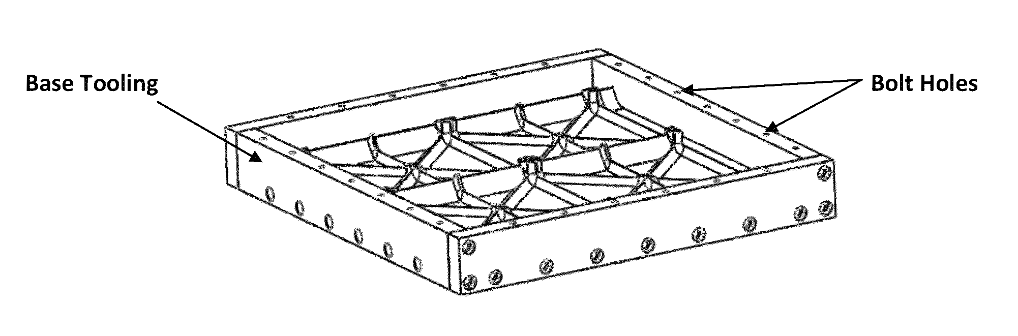
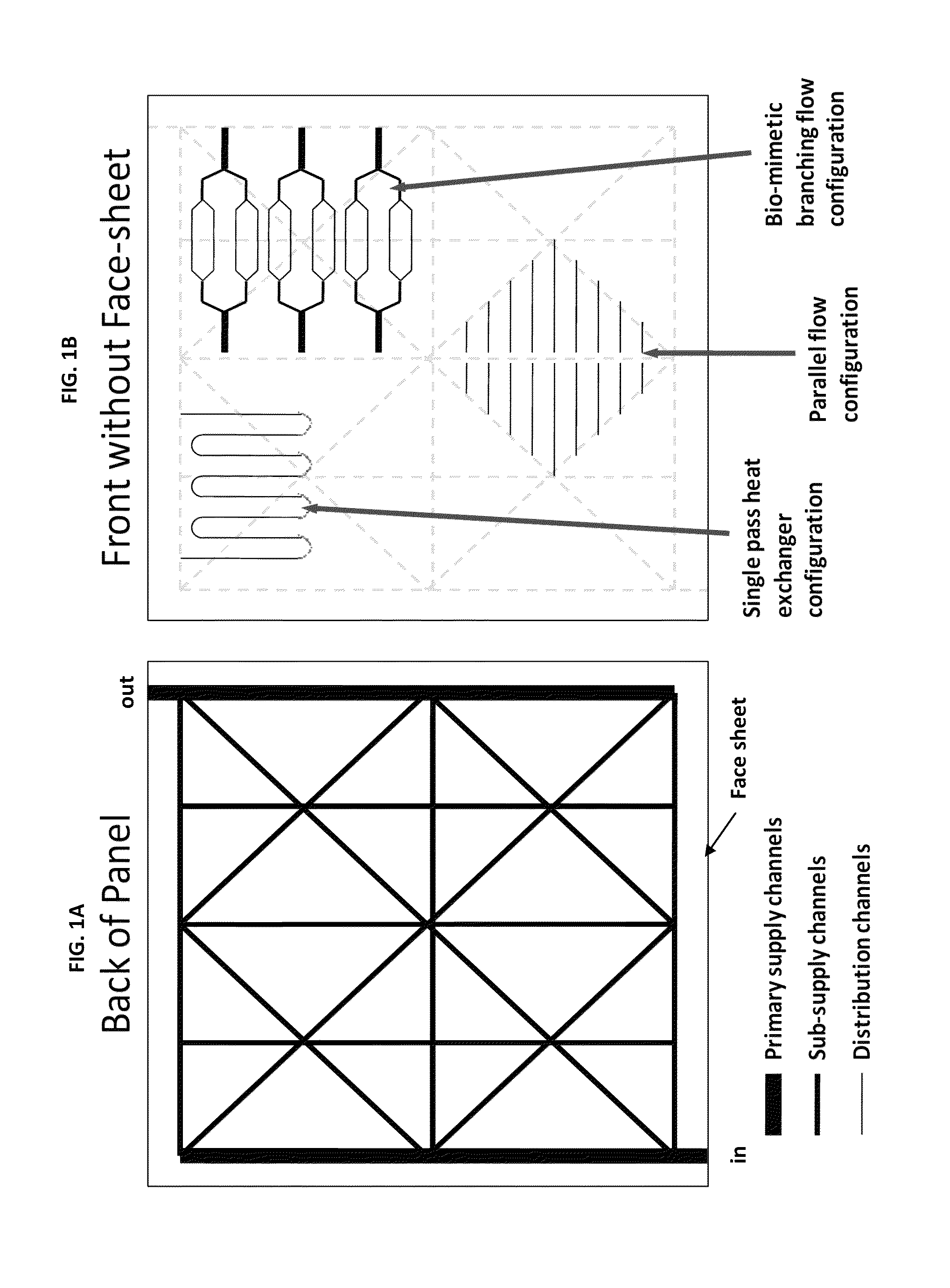
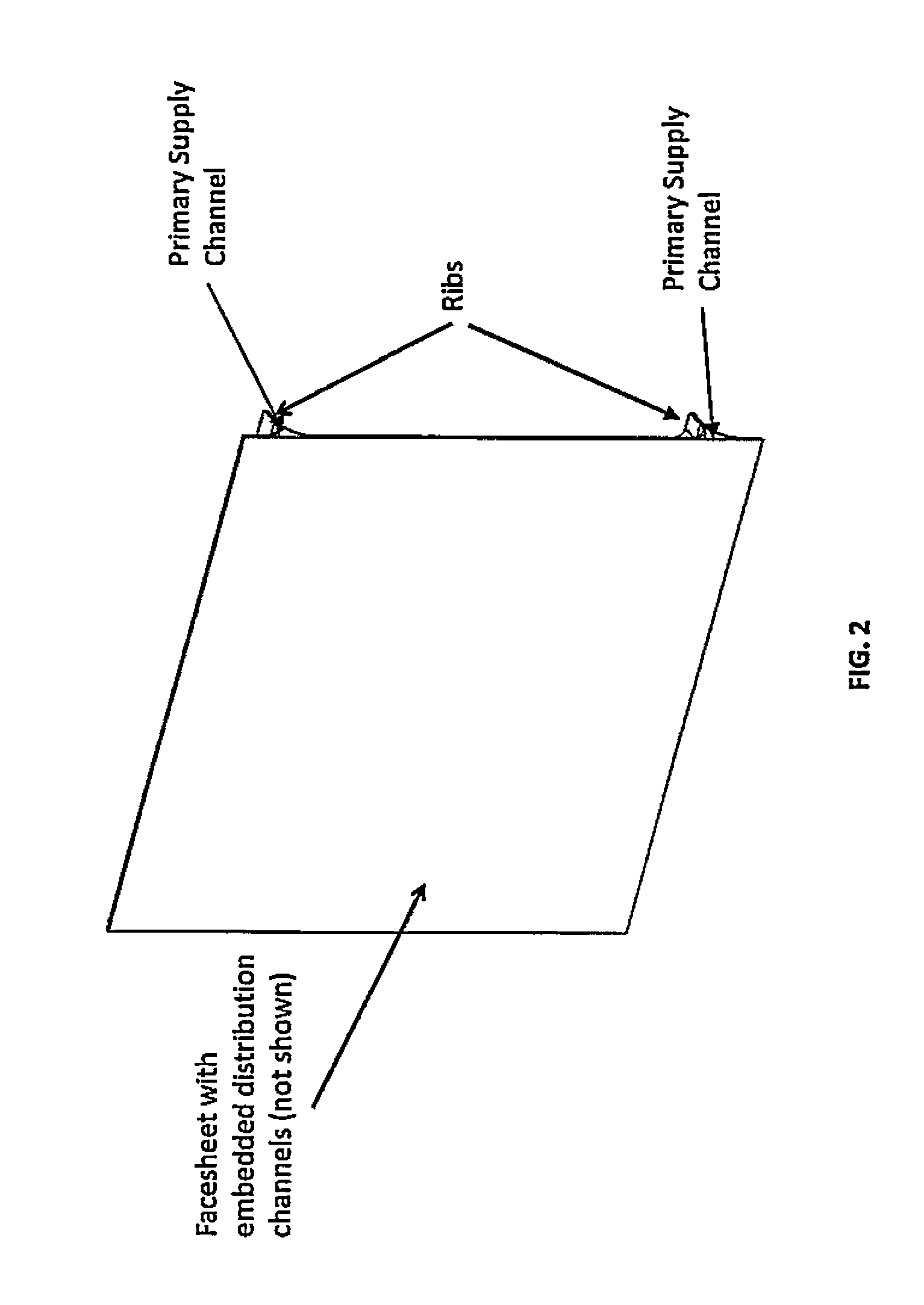
[0019]As discussed above, the disclosed invention is a method of fabricating a structural panel comprised of a series of primary supply, sub-supply, and distribution channels incorporated in the panel ribs and face sheet, and also a network of pumps and valves which control the flow of the working fluid through the panel. As a result of the requirements for low mass and complex geometry with internal channels, the preferred material of the grid-stiffened panel is carbon-fiber composite, but other embodiments could include structures composed of fiberglass or other composites.

[0020]Similar technologies have used heat pipes or cooling tubes embedded in structural panels (Rowe, N. C., “Structural Panel Having Integral Heat Pipe Network,” U.S. Pat. No. 5,506,032, issued Apr. 9, 1996 and Bodart, E. D., and Morgenthaler, G. T., “Metallic Structural Panel and Method of Fabrication,” U.S. Pat. No. 5,300,367, Apr. 5, 1994). The first of these technologies, disclosed in Rowe, addresses the in...


PUM

PropertyMeasurementUnit
sizeaaaaaaaaaa
surface areaaaaaaaaaaa
thermal stressesaaaaaaaaaa

Abstract

A method for fabricating a grid-stiffened panel which incorporates a network of fluid channels and passageways into the ribs and face sheet is described. The method is comprised of a base tooling assembly, an expansion tooling assembly, a composite prepreg, plugs, a face sheet and a network of valves and pumps, wherein the prepreg is draped over said expansion tooling and assembled with the base tooling assembly to form a rib structure. Channel plugs are placed therein such that gaps between adjacent expansion tooling blocks are filled, and the entire rib structure assembly is autoclaved. The face sheet may be comprised of a plurality of layers, whereby channels are machined into the lower layer(s). The upper layer(s) are bonded to the lower layer(s) to seal the channels, and said face sheet is bonded to the rib structure.

Description

STATEMENT OF GOVERNMENT INTEREST[0001]The conditions under which this invention was made are such as to entitle the Government of the United States under paragraph 1(a) of Executive Order 10096, as represented by the Secretary of the Air Force, to the entire right, title and interest therein, including foreign rights.BACKGROUND OF THE INVENTION[0002]The present invention relates generally to thermal management systems, and more specifically to a method of fabricating a structural panel with an integrated pumped-fluid loop thermal management system while maintaining the panel's stiffness-to-mass ratio.[0003]Due to the vacuum of the space environment, traditional spacecraft thermal control techniques usually rely upon conduction and radiation to dissipate and reject heat generated by on-board electronic equipment. The spacecraft is designed such that a conduction path exists between each electronic component, the spacecraft bus, and a radiator outside the spacecraft, which radiates th...

Claims


Application Information

Patent Timeline
Patent Type & Authority Patents(United States)
IPC IPC(8): B32B3/20
CPCB29C66/53F28F3/12F28F21/084F28F2210/02B29D99/0014
Inventor WILLIAMS, ANDREW D.UNDERWOOD, JR., RICHARD LEEBUSCH, GREG THOMAS
Owner THE UNITED STATES OF AMERICA AS REPRESETNED BY THE SEC OF THE AIR FORCE
Why Eureka
Try Eureka