Broadband or mid-infrared fiber light sources

a fiber light source and mid-infrared technology, applied in the direction of optical radiation measurement, instruments, spectrometry/spectrophotometry/monochromators, etc., can solve the problems of opos and opas being difficult to operate at wavelengths, affecting the efficiency of light sources, and opas being generally expensive and expensive, so as to reduce water absorption and increase power throughput and output power , the effect of broadening the input optical spectral width

Inactive Publication Date: 2014-03-11
OMNI MEDSCI INC
View PDF200 Cites 23 Cited by
  • Summary
  • Abstract
  • Description
  • Claims
  • Application Information

AI Technical Summary

Benefits of technology

[0006]A simpler technique for generating mid-IR light is to use laser diodes to pump optical fibers. The MIRFIL can exemplary involve the generation of mid-IR light in optical fibers by pumping with a variety of lasers including laser diodes, solid state lasers, or cladding-pumped fiber lasers. In one embodiment, SC generation is achieved to simultaneously generate a wide band of wavelengths, which can advantageously be used to mimic the black body radiation of hot metal objects or to perform spectral fingerprinting to identify one or more chemical species. The fiber based MIRFIL can be lighter, more robust, more compact, simpler and less costly than the OPA or OPO alternatives. Moreover, the MIRFIL can produce a single spatial mode with minimal requirements for optical alignments. In a preferred embodiment, nanosecond pulses are used to generate mid-IR light. In addition, the MIRFIL approach leverages the enormous investment in telecommunications technologies and the mature fiber platform.
[0012]In another embodiment, super-continuum (SC) generation from the visible or near-IR wavelength range can be accomplished using nanosecond pulse pumping. The SC generation can exemplary be initiated using modulational instability (MI). In a preferred embodiment, the seed for MI may arise from the amplified spontaneous emission from the optical amplifiers or from a near-IR light source, such as a laser diode. In a particular embodiment using fused silica fiber, the SC can cover the wavelength range substantially between approximately 0.8 microns to approximately 2.8 microns. In another particular embodiment using ZBLAN fluoride fiber, the SC can cover the wavelength range substantially between approximately 0.8 microns to approximately 4.5 microns. With control of the fiber loss from the material or from bend induced loss, as well with tailoring the composition of the fluoride fiber, the long wavelength edge of the SC may be pushed out to 5.3 microns or longer. In a preferred embodiment, it may be valuable to add a wavelength conversion stage. In addition, it may be advantageous to have a pulse compression stage following the MI pulse break-up.
[0014]In another embodiment, the power for the MIRFIL can be scaled up by using a higher power pump laser, such as a cladding pumped fiber amplifier, a cladding pumped fiber laser or a solid state diode-pumped light source. Based on the damage threshold of the particular fiber employed, the core size of the fiber can also be increased to increase the power throughput and output power.
[0019]Depending on the specific features implemented, particular embodiments of the present invention may exhibit some, none, or all of the following technical advantages. Various embodiments may be capable of covering other wavelength ranges or multiple wavelength ranges. For example, SC generation can cover the visible wavelength range from approximately 0.4 microns to 0.6 microns by using a dual pumping scheme. Some embodiments may be capable of generating bands of wavelengths rather a continuous range of wavelengths, and the bands of wavelengths may also be tunable or adjustable.

Problems solved by technology

However, OPOs and OPAs are generally expensive, complicated, and involve moving parts that are prone to mis-alignment.
However, QCL's are generally difficult to operate at wavelengths shorter than about 4.4 microns, they put out low output powers, they have relatively low efficiency, and they often required pulsed operation or cryogenic cooling.

Method used


Image

  • Broadband or mid-infrared fiber light sources
  • Broadband or mid-infrared fiber light sources
  • Broadband or mid-infrared fiber light sources

Examples


Embodiment Construction

[0042]As required, detailed embodiments of the present invention are disclosed herein; however, it is to be understood that the disclosed embodiments are merely exemplary of the invention that may be embodied in various and alternative forms. The figures are not necessarily to scale; some features may be exaggerated or minimized to show details of particular components. Therefore, specific structural and functional details disclosed herein are not to be interpreted as limiting, but merely as a representative basis for teaching one skilled in the art to variously employ the present invention.

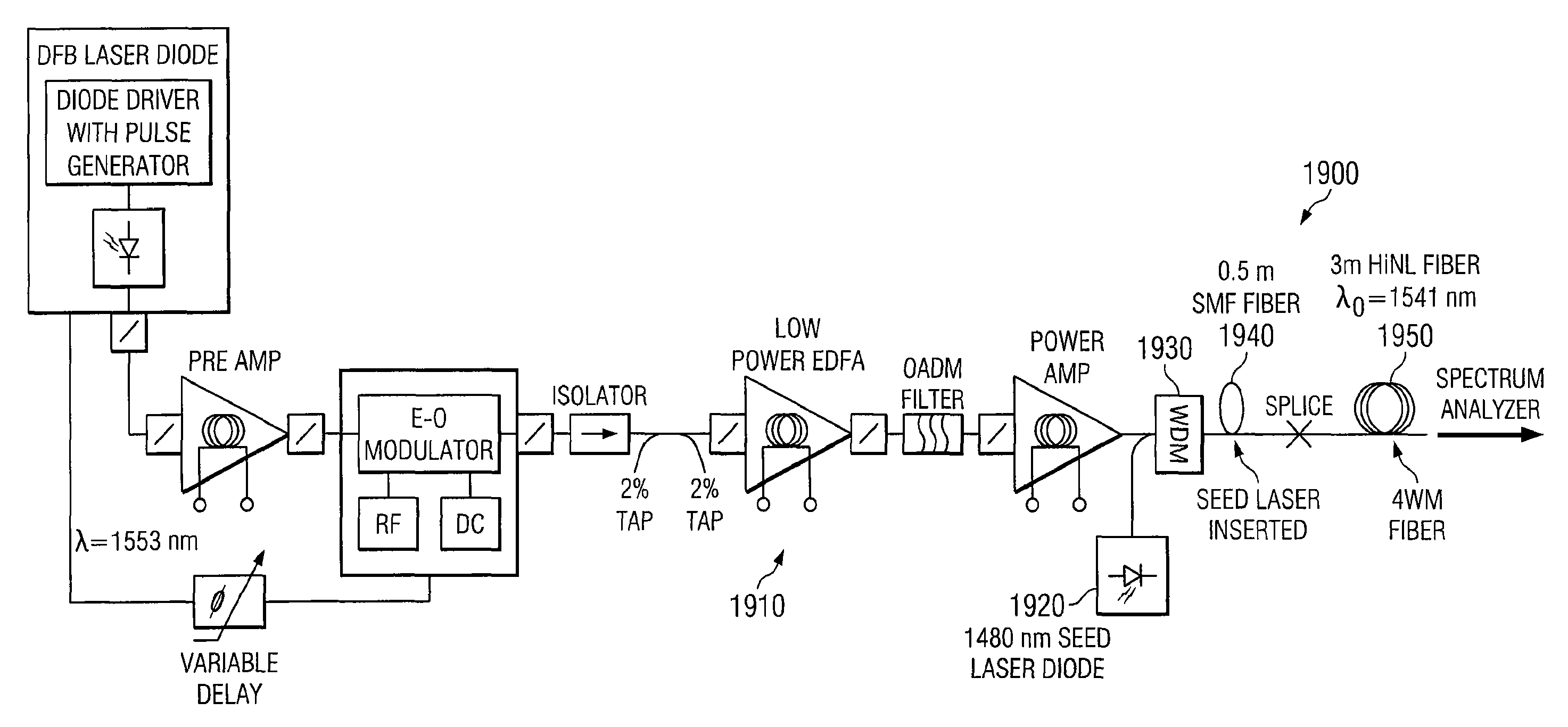
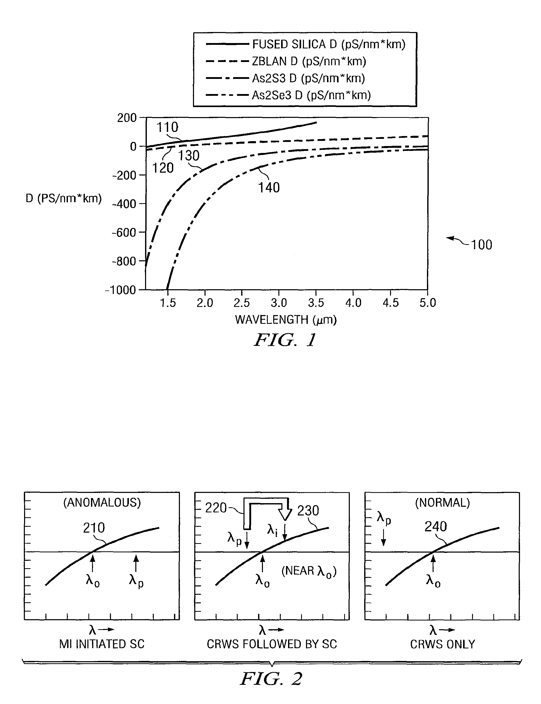
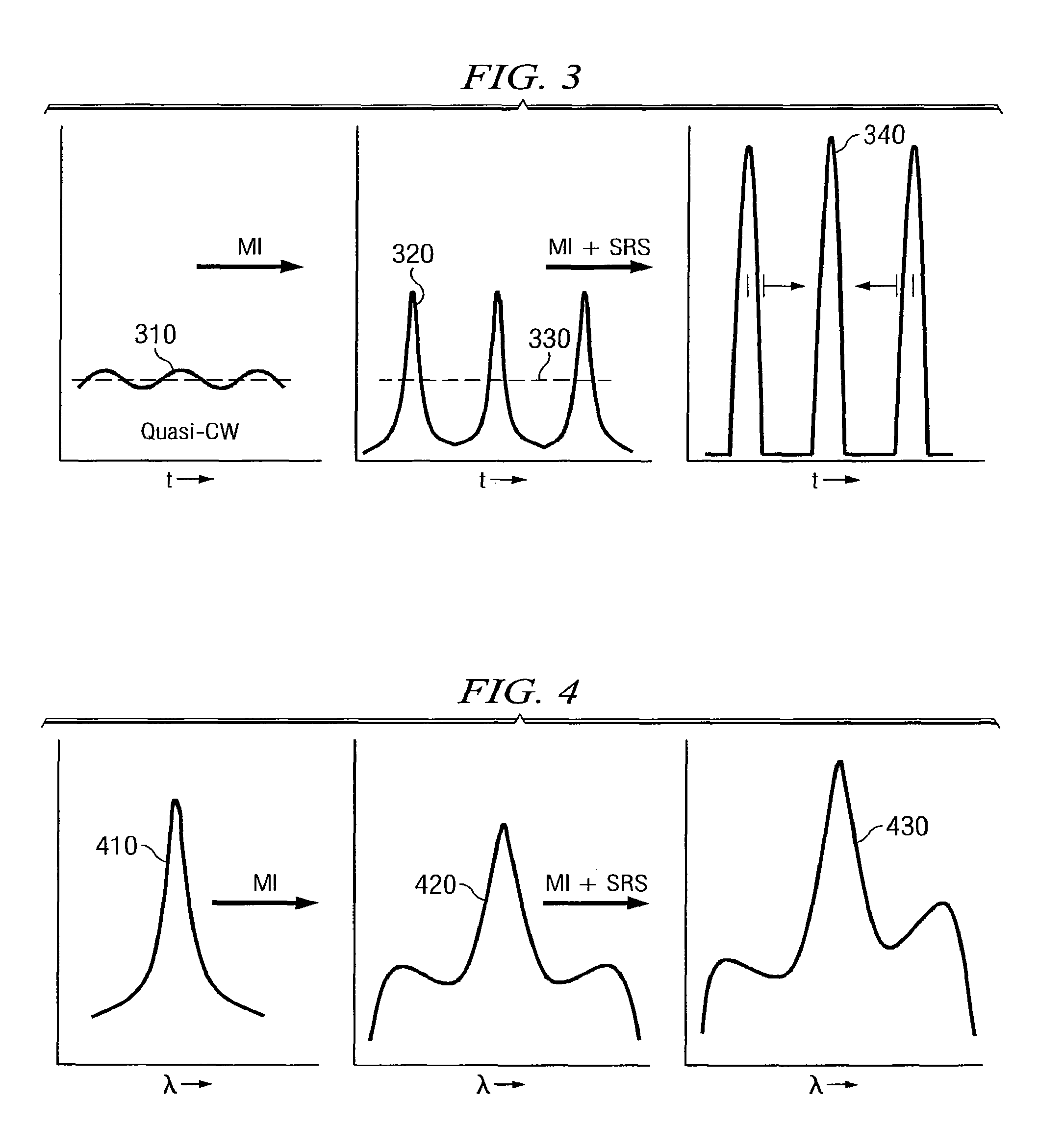
[0043]Mid-IR light can be generated based on super-continuum in fused silica fibers and mid-IR fibers. Nonlinear waveguides other than fibers can also be used to generate the super-continuum. In one embodiment, SC has been demonstrated experimentally from ˜0.8 to ˜4.5 microns in ZBLAN fluoride fibers and from ˜0.9 to ˜2.8 microns in high-nonlinearity (HiNL) fused silica fiber. The SC originates f...


PUM


Abstract

An optical system for use in a spectroscopy procedure includes one or more semiconductor diodes configured to generate an input signal beam with a wavelength shorter than 2.5 microns that is amplified and communicated through optical fiber(s) to a nonlinear element configured to broaden the spectral width to at least 50 nm through a nonlinear effect. A subsystem includes lenses or mirrors to deliver an output beam having a broadened spectrum selected to obtain a desired penetration depth and substantially minimize water absorption with a temporal duration greater than about 30 picoseconds to a sample to perform spectroscopy to characterize the sample. The output beam may have a repetition rate between continuous wave and one Megahertz or higher with a time averaged output power of 20 mW or more and a time averaged intensity of less than approximately 50 MW / cm2.

Description

CROSS-REFERENCE TO RELATED APPLICATIONS[0001]This application is a Continuation of U.S. application Ser. No. 13 / 241,900 filed Sep. 23, 2011 (now U.S. Pat. No. 8,391,660), which is a Continuation of U.S. application Ser. No. 12 / 366,323 filed Feb. 5, 2009 (now U.S. Pat. No. 8,055,108), which is a Continuation of U.S. application Ser. No. 11 / 599,950 filed Nov. 15, 2006 (now U.S. Pat. No. 7,519,253), which claims priority to U.S. Provisional Patent Application Ser. No. 60 / 738,389, filed Nov. 18, 2005, the disclosures of which are hereby incorporated by reference in their entirety.STATEMENT REGARDING FEDERALLY SPONSORED RESEARCH OR DEVELOPMENT[0002]This invention was made with Government support under Contract No. W31P4Q-05-C-0159 awarded by the U.S. Army Aviation and Missile Command and Contract No. W911NF-04-C-0078 awarded by the U.S. Army Robert Morris ACQ CTR. The Government has certain rights in the invention.TECHNICAL FIELD[0003]This invention relates in general to broadband or mid...

Claims


Application Information

Patent Timeline
Patent Type & Authority Patents(United States)
IPC IPC(8): G02B6/00
CPCG01J3/0218G02F2001/3528H01S2301/085H01S3/094069H01S3/094076H01S3/06725H01S3/302H01S3/06754G01J3/108G01B9/02091H01S3/1024H01S5/0085H01S5/146H01S5/1092G02F1/365G02F1/3528G01J3/0245G01J3/42G01J2003/102G01J2003/423G02B6/29349H01S5/0064G02F2202/32H01S3/094007H01S5/0092H01S5/4012
Inventor ISLAM, MOHAMMED, N.
Owner OMNI MEDSCI INC
Why Eureka
Try Eureka