Durable fine wire electrical conductor suitable for extreme environment applications

a technology of electrical conductors and fine wires, applied in the field of electric conductors, can solve the problems of failure of electrical conductor fatigue, failure of electrical conductors, etc., and achieve the effects of high redundancy for each connection, high flexibility, and increased flexibility of lead leads

Active Publication Date: 2014-04-08
CARDIA ACCESS
View PDF46 Cites 1 Cited by
  • Summary
  • Abstract
  • Description
  • Claims
  • Application Information

AI Technical Summary

Benefits of technology

[0018]In a further embodiment the center of the fiber core is hollow to increase flexibility of a lead of a given diameter. In still a further embodiment, multiple conductors are embedded separately side-by-side in the glass fiber core, where the glass serves to electrically insulate the conductors from each other.
[0029]Alternative methods of producing a coaxial electrically conductive glass fiber include drawing a core fiber, coating that core with a metal buffer and drawing additional silica or glass over the assembly and cladding that final assembly with an additional metal buffer. Fibers can be pulled with a hole in the center as well, increasing flexibility; hole diameter can vary. In one embodiment one or more wires can be put inside the hole through a fiber. The fiber can be redrawn to engage the wire if desired.

Problems solved by technology

Other non-medical applications may require that electrical conductors function with a great degree of precision and integrity in hostile environments, posing challenges to electrical conductor design that are shared with implantable medical devices.
For instance, electrical conductors deployed in environments where the conductor is exposed to repetitive motion may result in fatigue failure to the conductor, not unlike what can occur with pacemaker or defibrillator leads.
These electrical conductors may also need to operate under conditions in which minimization of size and weight are required in ways that are not met by currently available electrical conductors.
No left, high pressure, heart access through the heart wall has been successful.
This access path has several drawbacks; the placement of the probes is limited to areas covered by veins, and the leads occlude a significant fraction of the vein cross section and the number of probes is limited to 1 or 2.
Previously available wire leads have not withstood these repeated flexings over long periods of time, and many have experienced failure due to the fatigue of repeated bending.
A straight wire can be put in overall tension, leading to fatigue failure, whereas a filar wound cannot.
However, the bulk of the wire and the need to coil or twist the wires to reduce stress, limit the ability to produce smaller diameter leads.

Method used


Image

  • Durable fine wire electrical conductor suitable for extreme environment applications
  • Durable fine wire electrical conductor suitable for extreme environment applications
  • Durable fine wire electrical conductor suitable for extreme environment applications

Examples


Embodiment Construction

[0051]The invention encompasses electrical conductors for all implantable electrostimulation and sensing devices having implanted wire leads, and non-medical applications where light weight and durability are important characteristics contributing to the performance of the electrical conductor, especially in extreme environmental conditions.

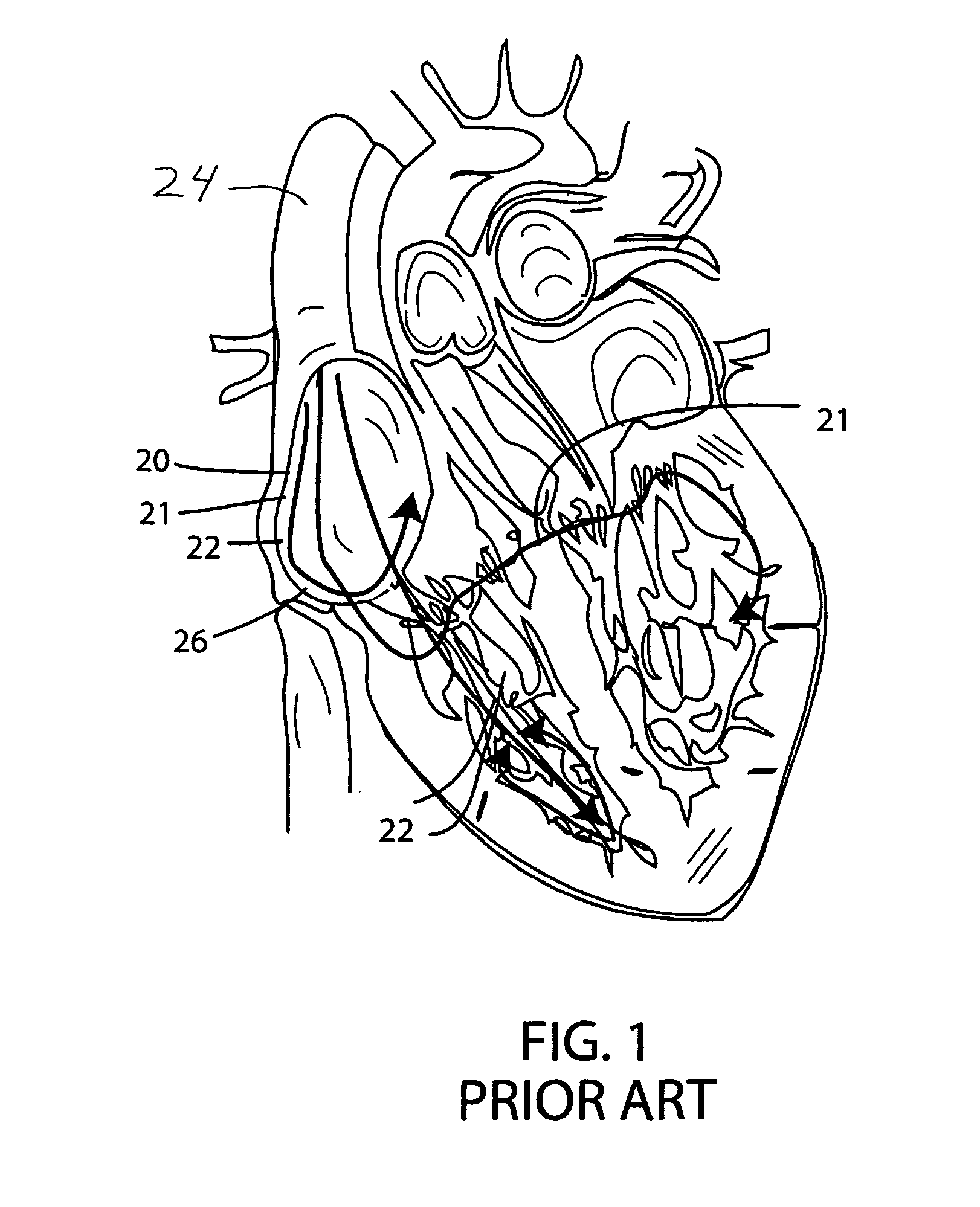
[0052]FIG. 1 shows schematically a human heart with some walls cut away. In FIG. 1 pacing leads are shown following a conventional path into the heart, and into the cardiac veins of the left ventricle, as has been typical of conventional practice and which, with some exceptions, is the basic path of leads of this invention.

[0053]In typical conventional practice, conductive leads 20, 21 and 22 are introduced into the heart through the superior vena cava 24, brought into the vena cava via subclavian or cephalic vein access points. For the right side of the heart, separate conventional pacing electrodes, as well as separate electrodes for biventricu...


PUM

PropertyMeasurementUnit
thicknessaaaaaaaaaa
outer diameteraaaaaaaaaa
diameteraaaaaaaaaa

Abstract

Durable fine wire electrical conductors are robust, durable, small in profile, and light weight, yet capable of operating under extreme environmental conditions. Formed of a glass, silica, sapphire or crystalline quartz fiber core with a metal coating and one or more polymer layers, a unipolar electrical conductor can have an outer diameter as small as about 300 microns or even smaller. The metal buffer coating may be deposited directly on the glass / silica fiber, or upon an intermediate layer between the glass / silica fiber and metal, consisting of carbon and / or polymer. The resulting metallized glass / silica fibers are extremely durable, can be bent through small radii and will not fatigue even from millions of iterations of flexing. Bipolar electrical conductors can include several insulated metallized glass / silica fibers residing side by side, or can be coaxial with two or more insulated metal conductive paths. An outer protective sheath of a flexible polymer material can be included.

Description

[0001]This application claims benefit of provisional application Ser. No. 61 / 271,077, filed Jul. 17, 2009. This application also is a continuation-in-part of Ser. No. 12 / 156,129, filed May 28, 2008, now abandoned, incorporated herein by reference. This is also a continuation-in-part of application Ser. No. 12 / 590,851, filed Nov. 12, 2009 and incorporated herein by reference.BACKGROUND OF THE INVENTION[0002]This invention concerns an electrical conductor suitable for use under conventional environmental conditions, but more importantly, is also functional and durable upon exposure to extreme environmental conditions. For purposes of this provisional patent application, an extreme environment is characterized by conditions that might include one or more of the following: hot or cold ambient temperatures, chronic vibration or bending, and exposure to aqueous conditions including body tissues, environmental contaminants such as dust, sunlight, or vacuum. Application of the electrical co...

Claims


Application Information

Patent Timeline
Patent Type & Authority Patents(United States)
IPC IPC(8): H01B7/04A61N1/05H01B11/00
CPCH01B7/048A61N1/05A61N1/0551H01B7/04A61N1/056H01B1/14H01B1/18H01B9/005
Inventor WALSH, ROBERT G.SHIMADA, JINENGLE, SCOTT
Owner CARDIA ACCESS
Why Eureka
Try Eureka