
Pollution abatement process for fossil fuel-fired boilers

a technology of fossil fuel-fired boilers and emissions reduction, applied in the direction of separation processes, emission prevention, flue gas purification components, etc., can solve the problems of increasing the quantity of particulates that can escape, environmental undesirable and subject to government regulation, and reducing so as to achieve the effect of minimizing the quantity of pa

Active Publication Date: 2014-04-15
INDAL ACCESSORIES
View PDF16 Cites 9 Cited by
  • Summary
  • Abstract
  • Description
  • Claims
  • Application Information

AI Technical Summary

Benefits of technology

[0017]The present invention overcomes the problems outlined above and provides improved boiler assemblies and methods characterized by a high degree of pollution abatement and low-cost operation. The boiler assemblies generally include a fossil fuel inlet, a boiler chamber coupled with the fuel inlet to receive fossil fuel for burning thereof, an economizer assembly comprising an inlet coupled with the boiler, an economizer chamber, and an economizer outlet, an air heater coupled with the economizer outlet, and a recirculation reactor coupled with the air heater.
[0023]In other embodiments, the sorbent materials of the invention may be introduced or injected with appropriate quantities of powdered activated carbon (PAC). In this way, the requisite amounts of PAC can be minimized.

Problems solved by technology

In fuel-fired boiler assemblies, and particularly coal-fired power generating plants or other industrial processes, combustion products include many compounds having an adverse influence on boiler operation or are environmentally undesirable and subject to government regulation.
Lime or limestone injected into the high temperature region of the boiler can also be effective in capturing the SO3, but the commercial materials that are generally utilized tend to magnify boiler deposit problems and increase the quantity of particulates that can escape.
Though very expensive, the “overbased” compounds are widely used at low dosages to capture vanadium in heavy-oil-fired combustion turbines.
In addition to oil-based slurries, Mg(OH)2 powders and water-based slurries have also been utilized as fireside additives in boilers, but because of their generally coarser particle size they are less efficient in capturing the SO3.
Water slurries of MgO have also been injected through specially modified soot blowers installed on oil and Kraft-liquor-fired boilers, in which they moderated high temperature deposits but had only a nominal impact on SO3-related problems because of an inability to apply the chemicals continuously.
Although high-surface-area lime can be effective in mercury capture, the usual commercial products can result in operational problems in the form of ash deposits and increased stack emissions.
The longstanding pollution abatement technologies employed with fossil fuel-fired boiler assemblies, while useful to a certain degree, do not achieve the highest degree of pollution control.

Method used


Image

  • Pollution abatement process for fossil fuel-fired boilers
  • Pollution abatement process for fossil fuel-fired boilers
  • Pollution abatement process for fossil fuel-fired boilers

Examples


Embodiment Construction

The Embodiment of FIGS. 1-3

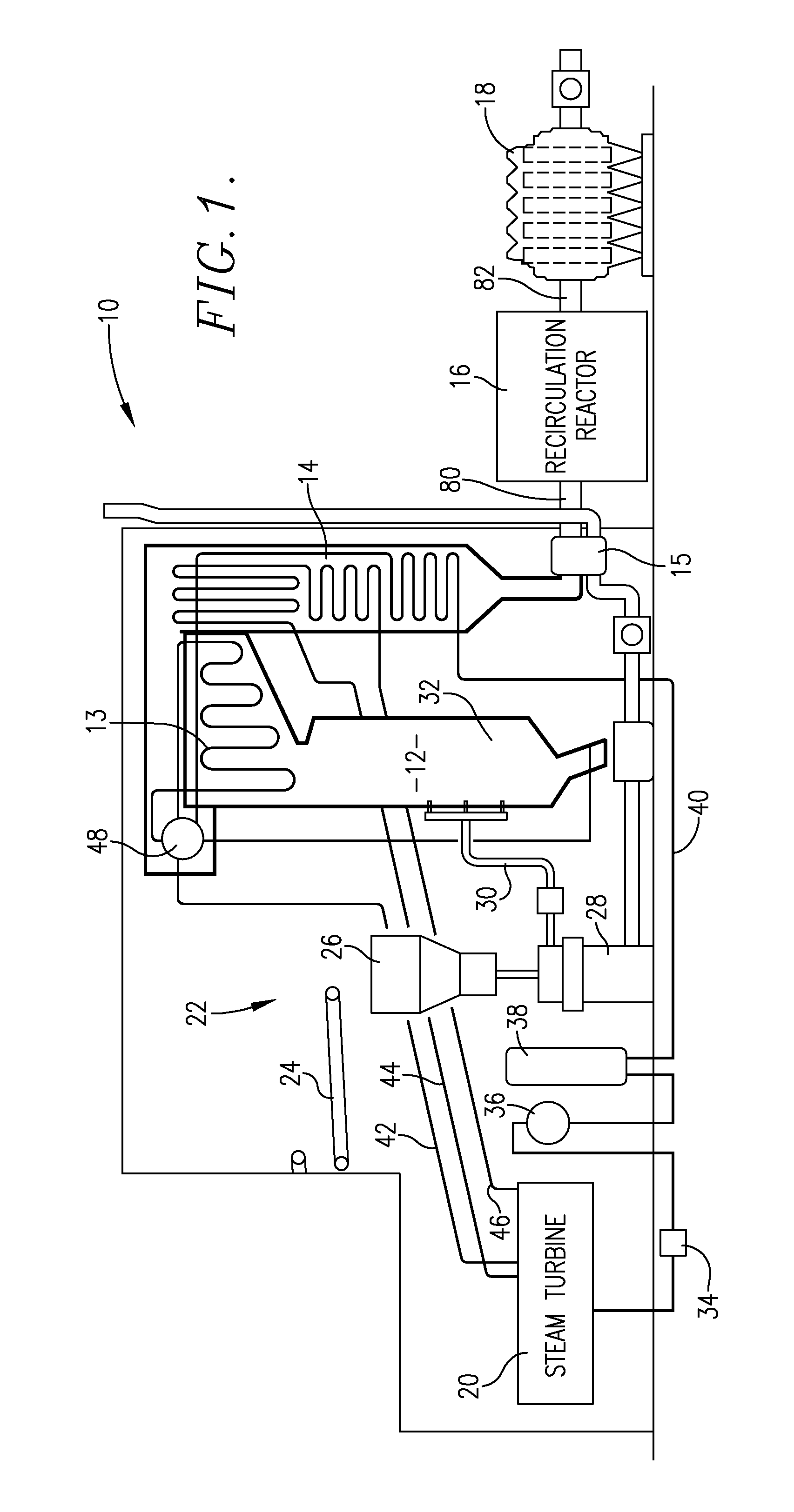
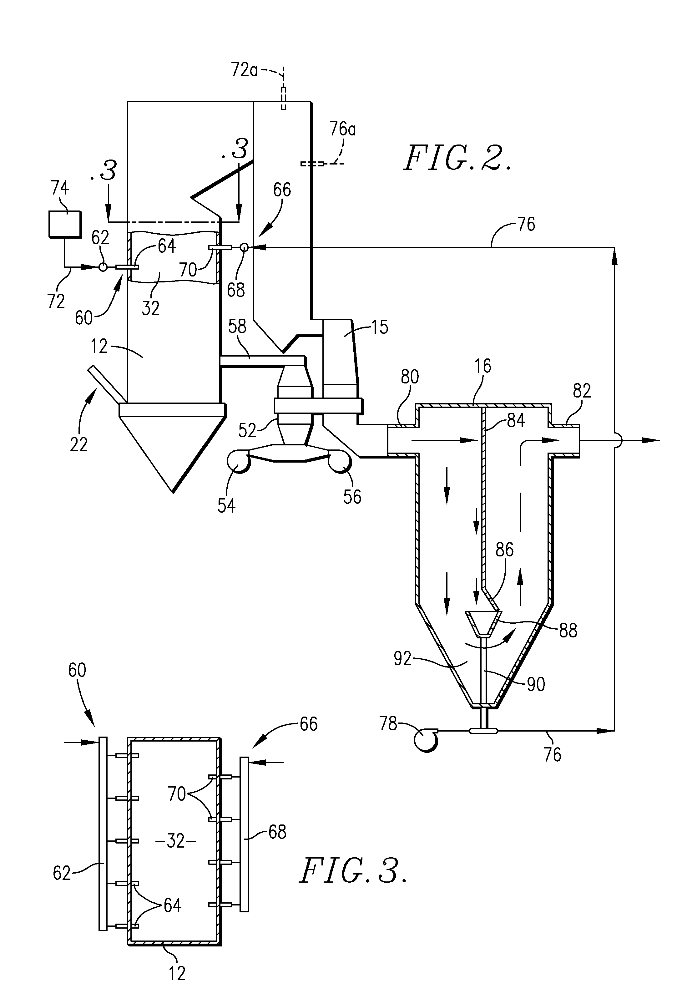
[0029]Turning now to the drawings, and particularly FIG. 1, an exemplary fossil fuel-fired boiler assembly 10 is schematically depicted in FIG. 1. Broadly speaking, the assembly 10 includes a boiler 12 including a superheater 13, economizer 14, air preheater 15, recirculation reactor 16, and a precipitator 18 (which can also be baghouse or other particulate collector) leading to a flue gas stack (not shown). The assembly 10 further has a steam turbine 20 (typically comprising interconnected low, intermediate and high pressure turbines), and a coal delivery assembly 22. The latter has a coal conveyor 24, coal hopper 26, coal pulverizer 28, and coal injector 30 operable to inject pulverized coal into the chamber 32 of boiler 12. A feedwater pump 34, the aerator 36 and heater 38 are located within feedwater line 40 leading to the economizer 14. Separate steam lines 42, 44, and 46 respectively extend between steam turbine 20 and boiler steam drum 48, and betwe...


PUM

PropertyMeasurementUnit
temperatureaaaaaaaaaa
adiabatic saturation temperatureaaaaaaaaaa
pressuresaaaaaaaaaa

Abstract

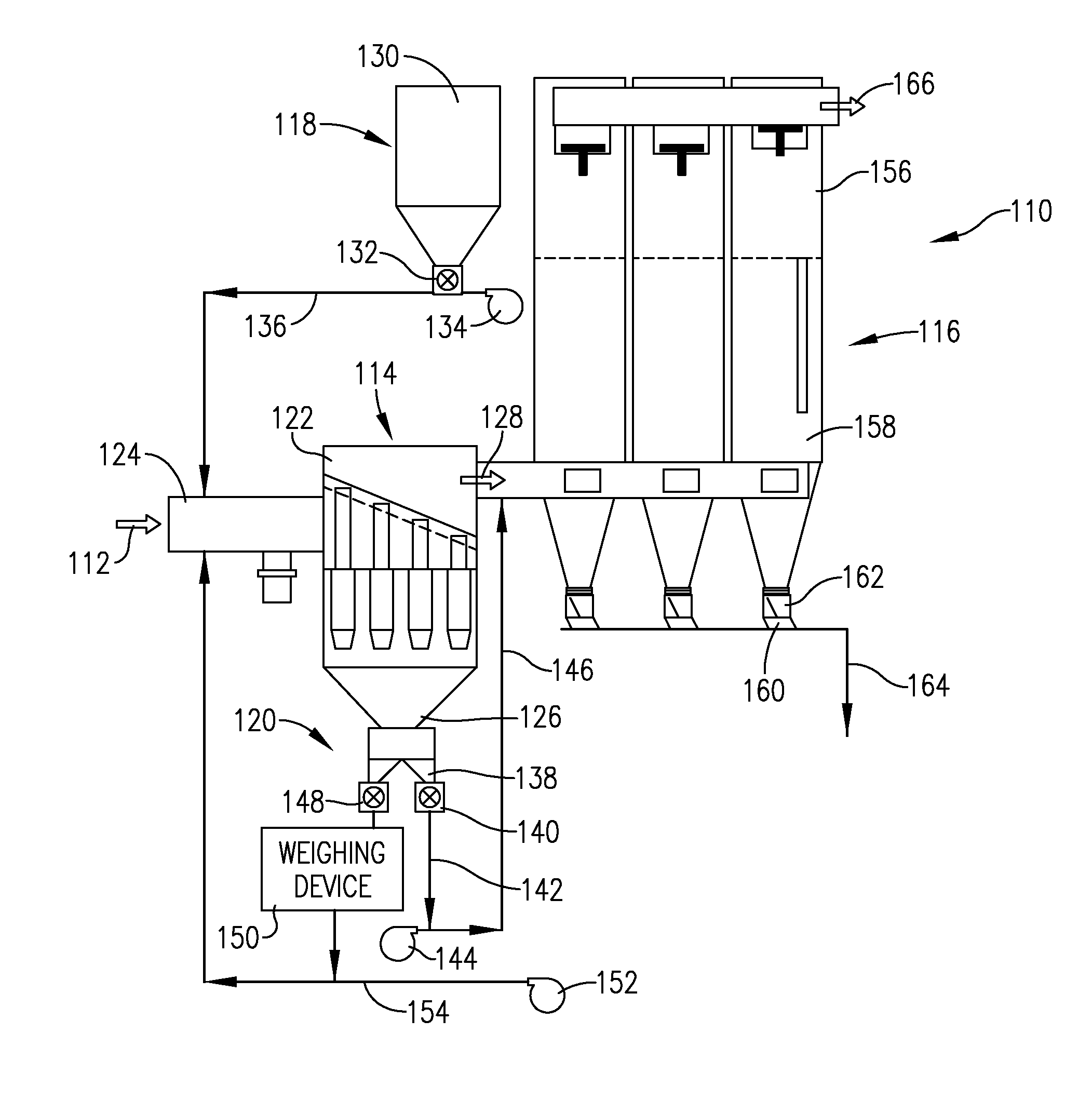
The present invention provides improved boiler assemblies (10) with enhanced pollution abatement properties through injection and recycling of particulate sorbent materials including sodium bicarbonate, trona, and mixtures thereof. The assemblies (10) include a boiler (12), economizer (14), air heater (15), and recirculation reactor (16). Fresh sorbent material is introduced via assembly (60) into the boiler assembly (10) at one or more injection locations, and serves to sorb NOx, SOx, and other pollutants in the flue gas. The flue gas and entrained sorbent material then pass through reactor (16) for separation of sorbent, which is then recycled for injection back into the assembly (10) upstream of reactor (16). In another aspect, the invention provides pollution abatement apparatus (110) and methods employing an upstream recirculation reactor (114), a supply of fresh sorbent (118), and a downstream collector (116). In the reactor (114), fresh sorbent reacts with incoming hot flue gas (112) to generate a reduced pollutant flue gas (128) and a solids fraction including reacted sorbent and pollutants, and unreacted sorbent. Recirculation apparatus (120) provided between the reactor outlet (126) and reactor (114) serves to generate a substantially constant mass or volume flow rate of the reactor solids fraction, which minimizes the use of fresh sorbent and maximizes the pollution abatement efficiency of the apparatus (110).

Description

CROSS-REFERENCE TO RELATED APPLICATION[0001]This is a continuation-in-part of application Ser. No. 12 / 427,408, filed Apr. 21, 2009, which is incorporated by reference herein in its entirety.BACKGROUND OF THE INVENTION[0002]1. Field of the Invention[0003]The present invention is broadly concerned with boiler assemblies and methods of operation thereof giving enhanced pollution removal. More particularly, the invention is concerned with such assemblies and methods wherein fresh sorbent material is injected into the assembly and reacts with flue gas pollutants; the flue gas and entrained sorbent are then passed through a recirculation reactor where sorbent is recovered for reinjection into the system. In preferred forms, the assemblies include a flue gas recirculation reactor such as a multi-clone device and a downstream particulate separator / collector such as a bag house or electrostatic precipitator. A constant mass or volume flow recirculation reactor recycle rate is established at ...

Claims


Application Information

Patent Timeline
Patent Type & Authority Patents(United States)
IPC IPC(8): F23J15/02
CPCF23J2215/20B01J2220/42B01J20/043B01J20/041B01J20/046B01D2251/402F23J7/00F22B37/008F23J15/02B01D2251/304B01D2257/302B01D2258/0283F23J2219/60B01D53/60B01D2253/102B01D53/83B01J20/28004B01D53/10B01D2251/404B01J20/20B01D2257/602Y02A50/20
Inventor NIJHAWAN, PRAMODH
Owner INDAL ACCESSORIES
Learn More