
Suturing an expanding, contracting graft tube in artery segment previously occluded

Inactive Publication Date: 2014-04-29
SHRIVER EDGAR L
View PDF17 Cites 1 Cited by
  • Summary
  • Abstract
  • Description
  • Claims
  • Application Information

AI Technical Summary

Benefits of technology

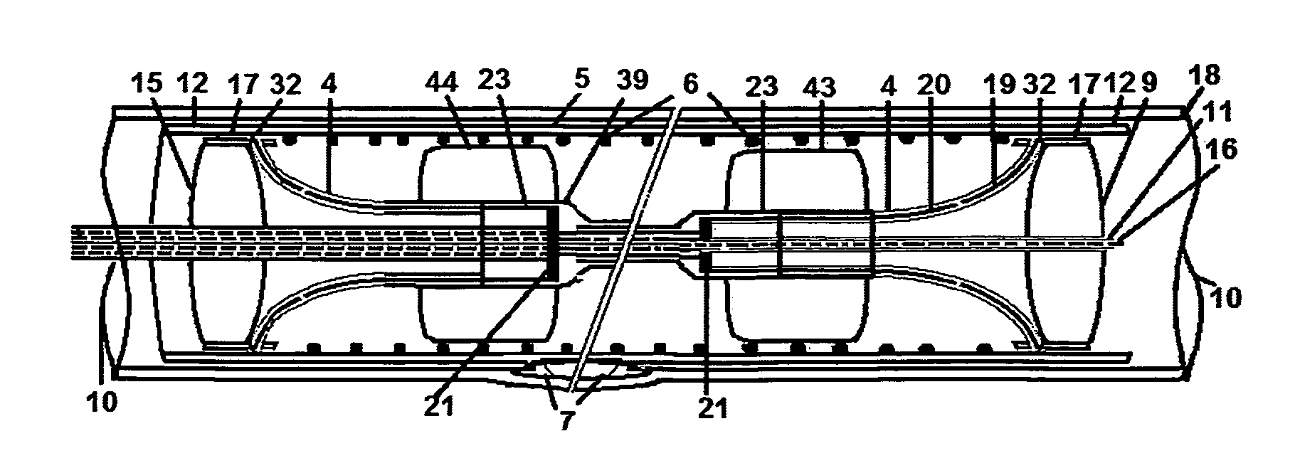
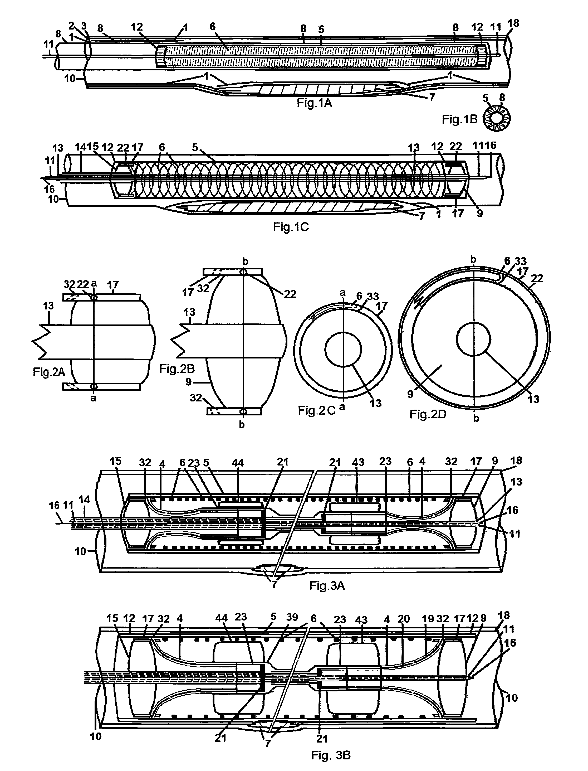
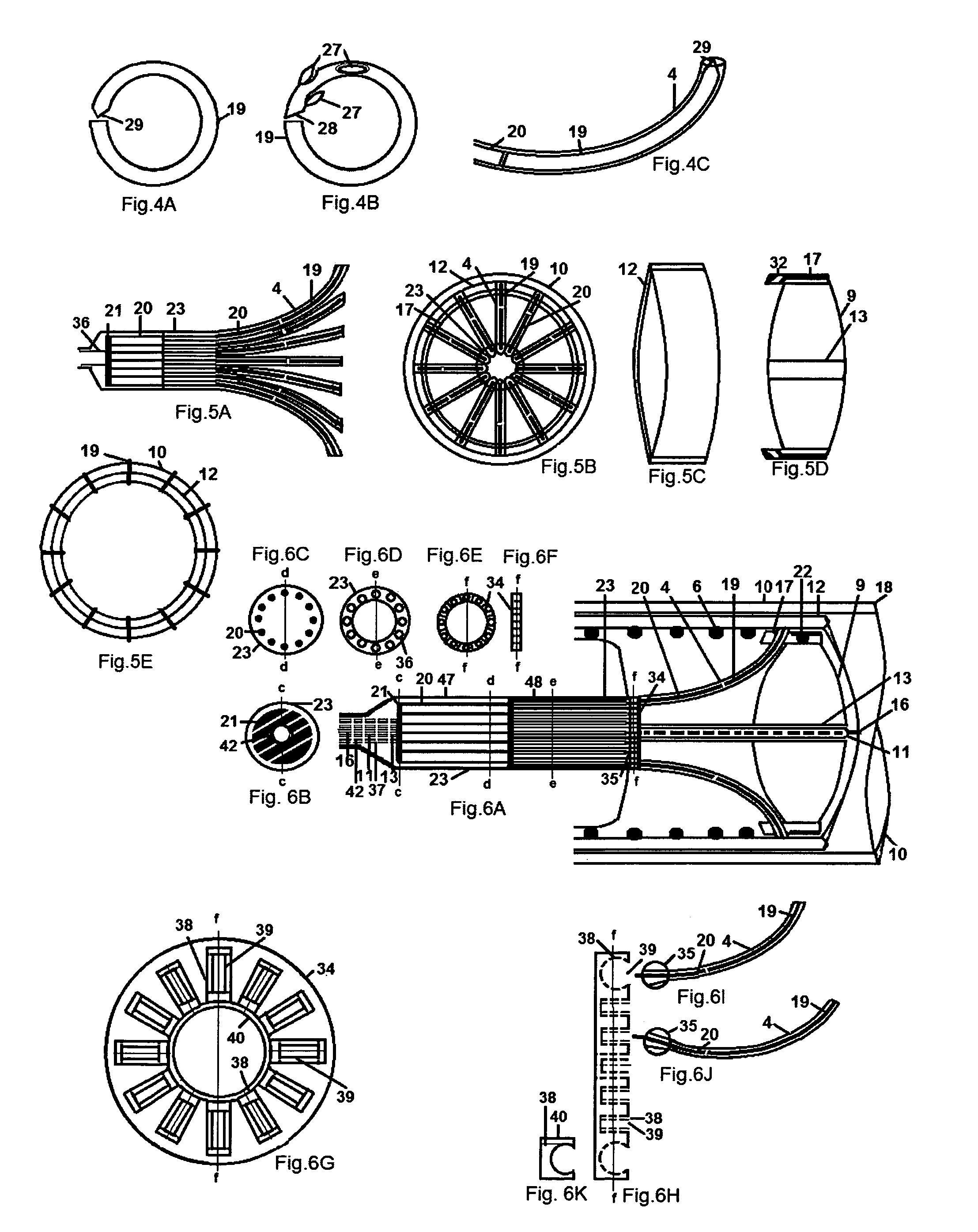
The present invention provides a new method for repairing damaged arteries using a graft tube and a spiral wire. The spiral wire serves as a support for the graft tube and is tightly wound to a smaller size for insertion into the artery. The spiral wire is expanded and contracted to match the circumference of the artery lumen and then the graft tube is inflated to push it against the artery wall using balloons. The balloons are fully or over-inflated to push the graft tube tightly against the artery wall. The method utilizes circular sutures made of shape memory material and a push-rod system to secure the graft tube and artery wall together. The use of circular sutures reduces the time required for placement and allows for simultaneous placement of multiple sutures. The graft tube and spiral wire can be made of biodegradable materials which serve as a scaffold for the vein or polymers that biodegrade after anastomoses have formed. The method also includes a means for slitting the artery wall segment that was previously occluded to allow the graft tube to move outside that segment.

Problems solved by technology

The plaque may rupture, cause blood clots, and / or calcify.
When the brain or heart is oxygen-deprived, death or impairment occurs rapidly.
This is much longer than the duration of percutaneous means but despite this advantage, bypass grafts require surgery that is risky and debilitating.
There are so-called “da Vinci” machines that can assist the surgeon's fingers to remain steady enough to place coronary bypasses through openings in the chest while the heart beats, but this machine is expensive and applicable to a limited number of cases.
Open surgery to place a bypass graft in the lower body is not as debilitating but is risky and involves a long recovery time in comparison to percutaneous entry through a skin puncture, which allows most patients to go home the next day with almost immediate recovery.
Balloons used alone result in the occlusion remaining open about 2½ years on average until 50% of cases close again, i.e., fail.
But in the longer arteries and occlusions of the legs, stents are likely to fracture so tend not to be used thus balloons are used alone.
Resistance to flow in an artificial artery of less than 4 mm is too much for them to be of practical use.
Percutaneous treatments have largely replaced surgical bypass graft treatments but have not achieved the long duration of the bypass graft placed surgically.
But that drug has created other problems, like blood clots that sometimes get caught in an artery of the brain causing a stroke.
Contrary to expectations, complete removal, by any of several methods, including scraping with a blade, laser, freezing, and a roto-rooter device, results in re-growth of the occlusion in a shorter time than by pushing it aside with a balloon.
Stent grafts are generally successful in preventing occlusions from growing back through the graft tube but the occlusions tends to grow back around the ends generally requiring repeat treatment in 50% of cases in less than 2½ years, and thus providing no improvement over a balloon alone without using the stent graft.
Balloon treatments have largely replaced surgical bypass graft treatments but they have not achieved the long duration of the bypass graft placed surgically.
None of these devices has been proven by clinical trials that resulted in approval by the Food and Drug Agency (FDA) for use—not because the bypass graft failed to provide the longer duration, but mostly because the graft used was not of sufficient size or there were real or assumed problems with one or more steps in the percutaneous process of placing the graft.
For instance, doubts have often been expressed about whether these prior art devices can accomplish re-entry into the artery after creating a passageway outside the artery wall.
The procedure was not extensively used, possibly because it requires substantial skill to use the collection of devices and it is counterintuitive to intentionally dissect two layers of an artery wall.
Once overinflated, graft stents cannot be reduced in size.
The tendency to overinflate is because leaving a gap between stent graft and artery wall will produce thrombus which is a risk of immediate failure and mortality.
But over-sizing the graft tube to more than the natural diameter of the artery reduces duration markedly.
Therefore this may or may not carry other consequences that are disadvantageous or dangerous.
The stent graft includes metal so is not biodegradable and thus not useful in combination with veins or tissue-engineered vessels (TEV) that are graft tubes made from the patient's own body cells.
But as long as surgery is needed to place them in the body, their use will be limited to a fraction of the relatively small number of cases still treated by surgery.
Prior art of spikes and hooks does not provide this security.
Avoiding recognized disadvantages in prior art is desirable, but whether this will result in longer patency can only be determined by experimentation and eventually clinical practice.

Method used


Image

  • Suturing an expanding, contracting graft tube in artery segment previously occluded
  • Suturing an expanding, contracting graft tube in artery segment previously occluded
  • Suturing an expanding, contracting graft tube in artery segment previously occluded

Examples


Embodiment Construction

[0065]Having thus described the figures, methods in accordance with the present invention are now described with reference thereto. It should be understood that steps described for each process may be omitted or the order changed or performed simultaneously without deviating from the spirit or scope of the invention. The following description should be read with reference to the drawings, in which the elements in different drawings are numbered in like fashion. The drawings, which are not necessarily to scale, depict selected embodiments and are not intended to limit the scope of the invention. Examples of construction, dimensions, materials, and manufacturing processes are provided for various elements but merely as a reflection of current manufacturing practices regarding processes and materials. Those skilled in the art will recognize that many of the examples provided have suitable alternatives in materials, manufacturing processes and specific configurations which may be utiliz...


PUM


Abstract

A spiral wire with shape memory wound to a small circumference for percutaneous introduction into an artery lumen has holding balloons gripping each end to control unwinding that increases and decreases circumference of a concentric graft tube against artery wall without under-sizing that creates dangerous gaps or over-sizing that promotes occlusion re-growth. Inflating holding balloons pushes ends of a plurality of tunnel arcs located at 2 mm intervals in rim around balloon circumferences tightly against graft tube whereupon push-rods within tunnel arcs simultaneously push out sharp circular sutures of memory material that return to original circular shape as they pierce and join graft tube and artery wall.

Description

CROSS-REFERENCE TO RELATED APPLICATIONS[0001]This is a new invention by the Inventor of prior art device U.S. Pat. No. 7,713,215, which discloses a means of percutaneously placing stiff sutures in seals which are in the shape of the end-to-side junction at each end of a second tube to openings made in a first tube on either side of an occlusion, and in application Ser. No. 12 / 924,746, after an occlusion is percutaneously removed or pushed aside from an artery lumen by another device, a graft tube is placed concentrically in the segment and its ends percutaneously sutured to healthy tissue on either side of the previously occluded segment. The device disclosed here has advantages over these, as well as other prior art inventions, and incorporation of some parts of prior patents may be required.FEDERALLY SPONSORED RESEARCH[0002]Not ApplicableSEQUENCE LISTING OR PROGRAM[0003]Not ApplicableBACKGROUND OF THE INVENTION[0004]1. Field of the Invention[0005]The field generally relates to con...

Claims


Application Information

Patent Timeline
IPC IPC(8): A61F2/06
CPCA61F2/07A61F2/958A61B2017/0649A61F2/88A61F2/06
Inventor SHRIVER, EDGAR, L.
Owner SHRIVER EDGAR L
Learn More