Centripetal air bleed from a turbomachine compressor rotor

a compressor rotor and turbomachine technology, which is applied in the direction of machines/engines, mechanical equipment, liquid fuel engines, etc., can solve the problems of increasing the specific consumption of the turbomachine, increasing the weight of the machine, so as to achieve the effect of less cost, simple structure and less energy consumption

Active Publication Date: 2014-05-13
SN DETUDE & DE CONSTR DE MOTEURS DAVIATION S N E C M A
View PDF18 Cites 8 Cited by
  • Summary
  • Abstract
  • Description
  • Claims
  • Application Information

AI Technical Summary

Benefits of technology

[0011]A particular object of the invention is to provide a solution to those

Problems solved by technology

However, turbulence and head losses in the annular chamber between the rotor disks are considerable, which leads to air being bled from a downstream stage of the compressor and therefore leads to an increase in the specific consumption of the turbomachine.
Nevertheless

Method used


Image

  • Centripetal air bleed from a turbomachine compressor rotor
  • Centripetal air bleed from a turbomachine compressor rotor
  • Centripetal air bleed from a turbomachine compressor rotor

Examples


Embodiment Construction

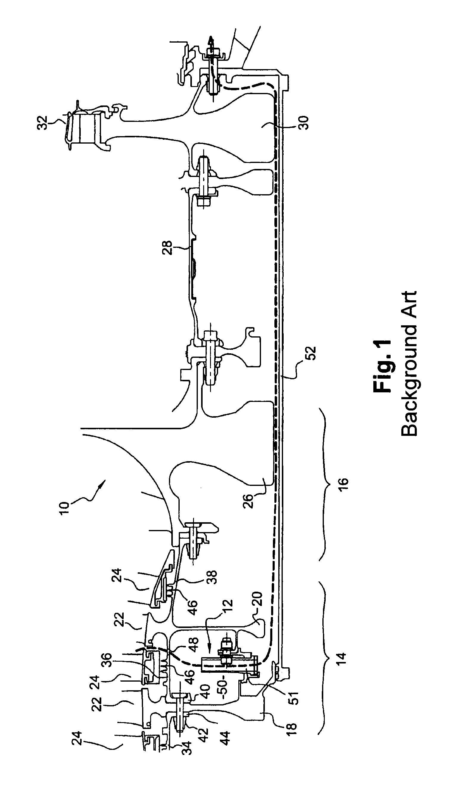
[0032]Reference is made initially to FIG. 1, which shows a portion of a turbomachine 10 fitted with centripetal air bleed means 12 of the prior art.

[0033]The turbomachine comprises in particular a compressor, a combustion chamber, and a turbine. The compressor 14, 16 is shown in part and comprises an upstream module having a plurality of axial compression stages 14 and a downstream module comprising a centrifugal compression stage 16. Each axial stage 14 of the compressor comprises a rotor wheel formed by a disk 18, 20 carrying blades 22 at its outer periphery, and a nozzle 24 situated downstream from the wheel and formed by an annular row of stationary nozzle vanes.

[0034]The rotor disks 18 and 20 are mounted on an axis that is common to them and to an impeller 26 of the centrifugal stage 16, which is itself fastened via an inner cylindrical casing 28 of the combustion chamber to a rotor wheel of the turbine. The turbine wheel is formed by a rim 30 carrying blades 32 on its outer pe...


PUM


Abstract

A compressor rotor for a turbomachine including at least two disks on a common axis carrying blades and connected together by a tubular wall, forming a surface of revolution, and a centripetal air bleed mechanism including air passages passing through the tubular wall, together with a wall extending along the tubular wall from the through passages up to one of the disks to channel the air stream inside the tubular wall.

Description

BACKGROUND OF THE INVENTION[0001]1. Field of the Invention[0002]The present invention relates to centripetal air bleed means in a compressor rotor of a turbomachine such as an airplane turboprop or turbojet.[0003]2. Description of the Related Art[0004]The bladed wheels of a compressor rotor are connected together by a tubular wall forming a substantially cylindrical or frustoconical surface of revolution that extends coaxially between the disks. This wall connecting the disks together may be formed integrally with a first disk or it may be put into place and fastened, e.g. by brazing or welding, at one of its axial ends on a lateral face of the first disk, and its opposite axial end may include an annular flange fastened, e.g. by nut-and-bolt type means, to a second disk.[0005]It is known to fit the rotor with centripetal-flow air bleed means for feeding systems for ventilating and / or cooling downstream stages of the compressor and turbine rims of the turbomachine, and also for purg...

Claims


Application Information

Patent Timeline
IPC IPC(8): F04D29/00
CPCY02T50/676F04D29/584F02C6/08F04D27/0215F01D5/082Y02T50/672F04D29/321Y02T50/60
Inventor BEHAGHEL, LAURENT DONATIENGILLE, LAURENTPEGOUET, BENJAMIN PHILIPPE PIERRE
Owner SN DETUDE & DE CONSTR DE MOTEURS DAVIATION S N E C M A
Why Eureka
Try Eureka