
Ceramic honeycomb structure and its production method

a honeycomb and honeycomb technology, applied in the direction of metal/metal-oxide/metal-hydroxide catalysts, machines/engines, chemical/physical processes, etc., can solve the problems of low heat shock resistance, less relaxation of the application of the cell wall, and insufficient strength of the honeycomb structure after sintering, etc., to achieve a well-balanced hardness

Active Publication Date: 2014-05-20
HITACHI METALS LTD
View PDF10 Cites 5 Cited by
  • Summary
  • Abstract
  • Description
  • Claims
  • Application Information

AI Technical Summary

Benefits of technology

The present invention is about a ceramic honeycomb structure and its production method. The structure has cell walls made of ceramic material that can withstand large vibrations and shocks without getting damaged. The outer surface of the structure has a high hardness and heat shock resistance, which is achieved through a process of properly changing the hardness of the structure in its thickness direction. This results in a well-balanced hardness and heat shock resistance of the outer peripheral wall of the honeycomb structure.

Problems solved by technology

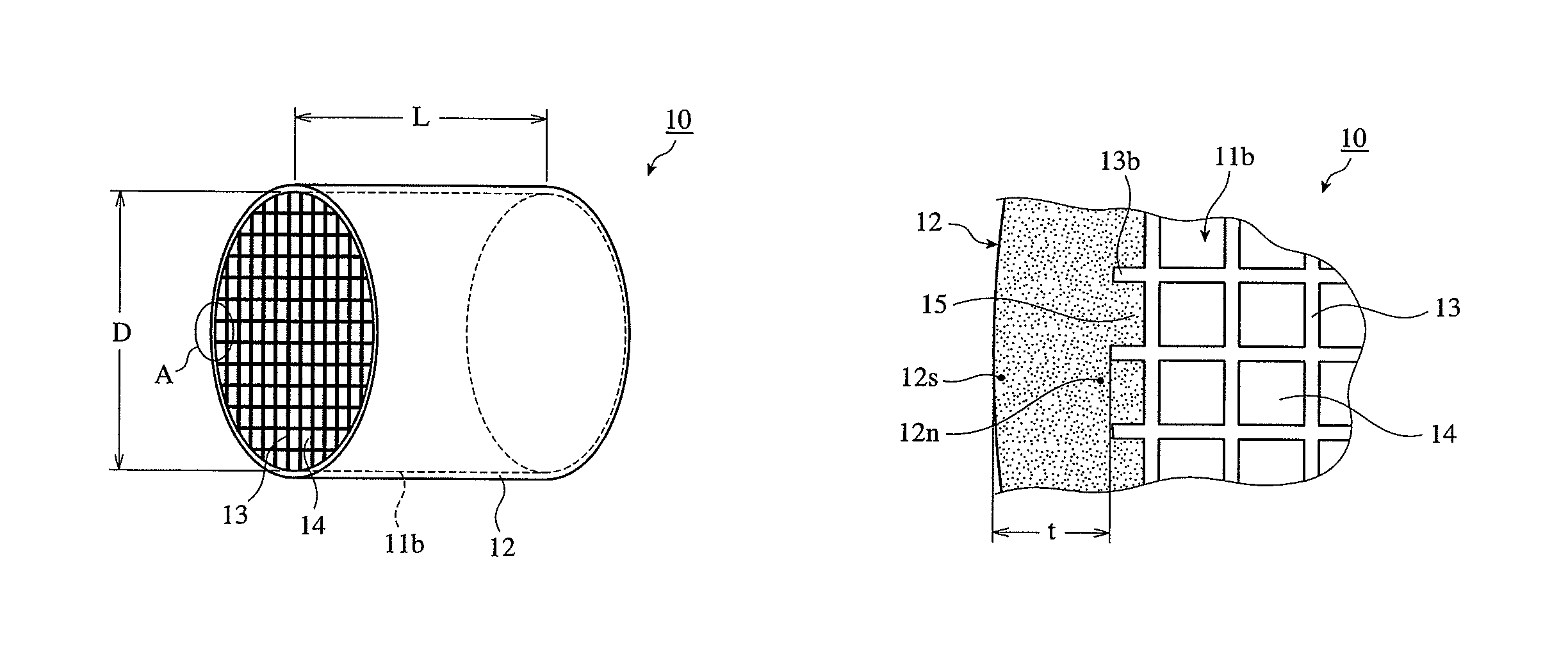
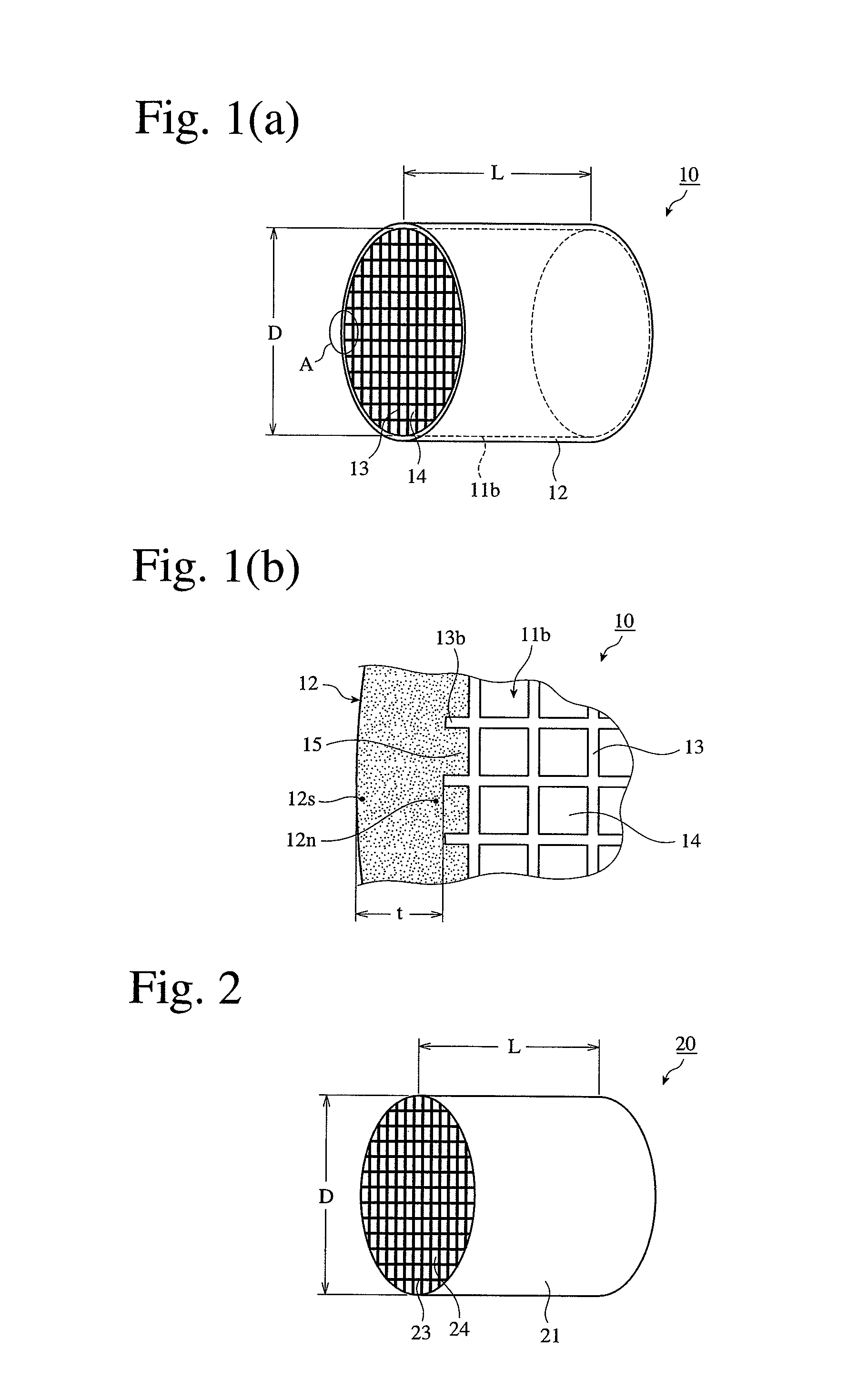
For instance, when a large ceramic honeycomb filter for diesel engines, which has an outer diameter D of 150 mm or more and a length L of 150 mm or more in FIG. 2, is produced, there are such problems that when a honeycomb structure is formed from a moldable material by extrusion molding, its cell walls 23 near an outer peripheral wall 21 are deformed by its own weight, and that the honeycomb structure does not have sufficient strength after sintering.
As a result, the outer peripheral wall has high strength on the inner side, so that heat shock applied to the cell walls is less relaxed, resulting in low heat shock resistance.
Accordingly, heat shock applied to cell walls is less relaxed, providing the outer peripheral wall with insufficient heat shock resistance.
Further, because large, heavy honeycomb structures having outer diameters of 150 mm or more and lengths of 150 mm or more for use in ceramic honeycomb filters for diesel engines are easily influenced by engine vibration and vibration due to contact with road surfaces, the outer peripheral walls described in JP 2004-75524 A, JP 2006-255542 A and JP 5-269388 A are insufficient in hardness, being likely to damaged during use.
Particularly, ceramic honeycomb filters for diesel engines used in construction machines, etc. are subjected to very large vibration and shock during use, so that their outer peripheral walls are likely damaged.
If the outer peripheral walls are made thicker to have higher hardness to prevent damage, they are easily cracked due to heat shock, resulting in low heat shock resistance.

Method used


Image

  • Ceramic honeycomb structure and its production method
  • Ceramic honeycomb structure and its production method

Examples


example 1

[0032]Kaolin powder, talc powder, silica powder and alumina powder were mixed to prepare cordierite-forming material powder comprising 50% by mass of SiO2, 35% by mass of Al2O3 and 13% by mass of MgO. This powder was mixed with methylcellulose and hydroxypropyl methylcellulose as binders, a lubricant, and graphite as a pore former. After thorough dry-blending, water was added to carry out sufficient kneading to prepare a moldable ceramic material.

[0033]This moldable material was extrusion-molded, and cut to a predetermined length to obtain a honeycomb molding integrally having a peripheral wall portion and cell walls. This molding was dried and sintered to obtain a sintered cordierite honeycomb having an outer diameter D of 280 mm, a length L of 300 mm, a cell wall thickness of 0.3 mm and a cell pitch of 1.5 mm as shown in FIG. 1. Using a cylindrical grinding machine, the outermost cell walls 13 were removed from this sintered honeycomb to provide a ceramic honeycomb body 11b with l...

examples 2-11

, CONVENTIONAL EXAMPLES 1 AND 2, AND COMPARATIVE EXAMPLES 1 AND 2

[0034]Ceramic honeycomb structures were produced in the same manner as in Example 1, except for changing the type of ceramic particles in the coating agent for forming an outer peripheral wall, the average particle size and amount of colloidal silica in the coating agent, blending pressure and drying conditions as shown in Table 1. Conventional Example 1 used the coating material described in JP 2004-75524 A, and Conventional Example 2 formed a dense surface layer using the coating material described in JP 2006-255542 A.

[0035]

TABLE 1Colloidal SilicaAverageBlendingCoated CeramicParticleAmount(1)Pressure(2)DryingNo.ParticlesSize (nm)(%)(kPa)ConditionsExample 1Cordierite420Atmospheric150° C., and 10PressureminutesExample 2Cordierite420−80150° C., and 10minutesExample 3Cordierite1020−80150° C., and 10minutesExample 4Cordierite2520−80150° C., and 10minutesExample 5Cordierite3020−80150° C., and 10minutesExample 6Cordierite50...


PUM

PropertyMeasurementUnit
thicknessaaaaaaaaaa
particle sizeaaaaaaaaaa
heat shock resistant temperatureaaaaaaaaaa

Abstract

A ceramic honeycomb structure comprising a ceramic honeycomb body having cell walls defined by a large number of longitudinally extending cells, and an outer peripheral wall formed on an outer peripheral surface of the ceramic honeycomb body, the outer peripheral wall being formed by coating longitudinally extending grooves defined by cell walls on the outer peripheral surface of the ceramic honeycomb body with a coating material, and the outer peripheral wall having higher hardness in its outer peripheral portion than in its inside portion in a thickness direction.

Description

CROSS REFERENCE TO RELATED APPLICATION[0001]This application is a National Stage of International Application No. PCT / JP 2007 / 074849 filed Dec. 25, 2007, claiming priority based on Japanese Patent Application No. 2006-351700 , filed Dec. 27, 2006, the contents of all of which are incorporated herein by reference in their entirety.FIELD OF THE INVENTION[0002]The present invention relates to a ceramic honeycomb structure and its production method, particularly to a honeycomb structure having an outer peripheral wall formed by a coating material applied to a peripheral portion appearing by removing a peripheral wall portion from a ceramic honeycomb by machining, and its production method.BACKGROUND OF THE INVENTION[0003]To protect regional or global environment, harmful materials are removed from exhaust gases emitted from engines of automobiles, etc., using exhaust-gas-cleaning catalyst converters and particulate-matter-capturing ceramic honeycomb filters comprising ceramic honeycomb ...

Claims


Application Information

Patent Timeline
Patent Type & Authority Patents(United States)
IPC IPC(8): C04B41/85F01N3/28B01D46/24F01N3/022C04B35/195C04B41/00C04B41/50C04B111/00
CPCB01D46/2425B01J35/04C04B41/009C04B2111/0081C04B41/85B01D46/2466B01D2046/2496C04B2111/00793C04B41/5089F01N2330/30F01N3/2828B01D46/2451B01D46/2462C04B35/195C04B41/5035B01D46/2444Y10T428/24149B01D46/2498B01D46/2482B01J35/56C04B38/0006C04B35/00C04B41/5024C04B41/5022
Inventor OKAZAKI, SHUNJI
Owner HITACHI METALS LTD
Learn More