Sealing of thief zones

a technology of thief zones and sealing, which is applied in the direction of earthwork drilling, fluid removal, drilling composition, etc., can solve the problems of large water production risks of production wells, large amount of injected fluid in the production well, and thief zones also affecting the sweep efficiency

Active Publication Date: 2014-05-27
MAERSK OLIE & GAS AS
View PDF20 Cites 1 Cited by
  • Summary
  • Abstract
  • Description
  • Claims
  • Application Information

AI Technical Summary

Benefits of technology

[0016]The object of the present invention is to provide a simple method capable of at least partially sealing selected subsurface zones.
[0023]In another embodiment of the method the ionic strength of the sealing fluid is increased by the addition of water-soluble salts. In one embodiment the ionic strength of the sealing fluid is larger than 20 M, which lowers the solubility product of calcium sulfate.

Problems solved by technology

Thief zones in the form of streaks of high permeability are common in carbonate reservoirs and can speed up, and increase the risk of the production well producing large volumes of water, if such thief zone connects the production well to a source of water.
Thief zones are also detrimental to the sweep efficiency, when fluid is injected into the reservoir from injection wells to displace oil.
If the reservoir is compromised by a thief zone connecting the injection well with the production well, then the production well will produce large amounts of the injected fluid.
Such short-circuiting in the reservoir further bypasses considerable amounts of hydrocarbons, as the thief zone will prevent an efficient sweep of the area beyond the thief zone.
Thus, the existence of thief zones can cause inefficient production of hydrocarbons from a reservoir, and further reduce the recovery of hydrocarbons.
Consequently, much effort has gone into developing methods to and products that reduce the permeability of thief zones.
As the typical thief zone is not confined to a few feet, but rather may extend over a large distance from the well; measures that seal the thief zone near the well are of limited value.
These methods typically suffer from difficulty of placing the monomer and catalyst the desired place, and from the complexity of achieving the correct timing.
Another problem associated with time delayed gelling and in situ polymerization methods are the fact that an injected fluid front will expand radially from the injection site.
Consequently, this can result in the gel and polymer sealing other areas than the thief zone, which is also detrimental to sweep efficiency.
Consequently, the method appears likely to suffer from at least some of the drawbacks mentioned for the time delayed gelling and in situ polymerization methods.
The excess of lime forms with the clay hydrates increasing effeciveness of the screen.

Method used


Image

  • Sealing of thief zones
  • Sealing of thief zones
  • Sealing of thief zones

Examples


example 1

Static Experiments

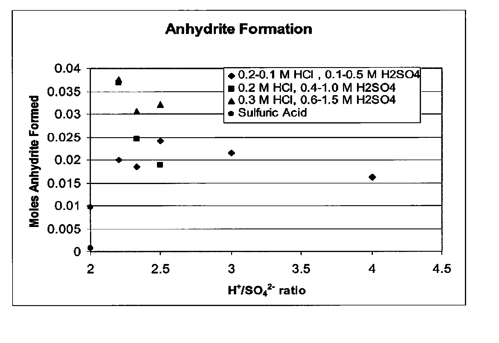
[0108]Static experiments were performed on cubic chalk samples of 8 cm3. The samples were sawed and then put in an ultrasonic bath to remove the saw dust. Thereafter, the samples were dried and weighed. Next, the samples were saturated with water by using a vacuum chamber. After the experiments all samples were rinsed, filtered and weighted. The remaining solution was analysed for residual sulfate ions. In the static experiments different concentrations of acid mixtures were used, and the cubic chalk samples were submerged in the acid mixtures. The temperature was 80° C.

[0109]

TABLE 1Acid mixtures used in static experimentsSample ID (#)HCl (M)H2SO4 (M)Acid ratio700.12901.02100.20.14110.10.13120.10.22.5140.10.32.33130.10.52.2160.20.42.5180.20.62.33190.21.02.2230.30.62.5240.30.92.33260.31.52.2

[0110]The results from the individual chalk samples are presented in Table 2. To compare the different chalk samples, three different methods are used:[0111]Difference of weight ...

example 2

Flow Experiments—General Experimental Setup

[0115]In the dynamic flow experiments with a large core holder, various parameters concerning acid injection into chalks have been investigated:[0116]Flow rate.[0117]Time of injection.[0118]Acid ratio.[0119]Concentration.[0120]Back pressure.[0121]Type of opening.

[0122]The core dimensions in these tests are 48 mm diameter and 150-180 mm in length. To prevent an outflow of fines it was chosen to flush the cores with brine instead of water before the acid injection.

[0123]The general experimental setup for the flow experiments on fractured chalk cores is described in the following with reference to the schematic diagram shown in FIG. 7. Injection fluid is pumped through the fracture of a chalk core, and the effluent is collected. The injection pressure is measured with pressure transducer 1, and the effluent pressure is measured with pressure transducer 2. The setup caps the differential pressure between pressure transducer 1 and 2 to 40 bar. T...

example 3

Flow Experiments—Obtaining Data

[0124]Flow experiment 10 was the first experiment with a 3 mm hole drilled into the core. The flow rate was 0.250 ml of 0.3 / 0.9 M HCl / H2SO4 per minute. This flow rate and the acid mixture were based on the previously conducted static experiments initial the flow experiments using a smaller core holder. Flow experiment 10 is considered to be the base case. The other experiments are variations on this base case.

[0125]The base case will be worked out with the recordings of the pressure data and an image of the result of the experiment. The parameters and results of the flow experiments are shown in table 3.

[0126]FIG. 8 shows the pressure data recorded during flow experiment 10. Due to temporarily malfunctioning data acquisition some time gaps are present in the recorded data. “Press 1” is the injection pressure in bars of pressure transducer “1”, “Press 2” is the pressure in bars of pressure transducer “2”, at the end of the core. “Dp40Bar” is the differe...


PUM

PropertyMeasurementUnit
differential pressureaaaaaaaaaa
injection pressureaaaaaaaaaa
ionic strengthaaaaaaaaaa

Abstract

The present invention provides a method for selectively sealing a thief zone in a hydrocarbon reservoir located in a calcium-rich formation and penetrated by a borehole comprising injecting into the thief zone a sealing fluid comprising a mixture of and hydronium ions (H+) and a source of sulfate ions (SO42−) which mixture can provide precipitation of a designated calcium sulfate compound.

Description

RELATED APPLICATIONS[0001]This application claims the benefit under 35 U.S.C. §371 of International Application No. PCT / EP2009 / 065414, having an International Filing Date of Nov. 18, 2009, which claims priority to Danish Application No. PA 2009 70213, filed Nov. 18, 2009, Danish Application No. PA 2008 01618, filed Nov. 19, 2008, and U.S. Provisional Application No. 61 / 116,226, filed Nov. 19, 2008, the contents of all of which are incorporated herein by reference in their entirety.FIELD OF THE INVENTION[0002]The present invention relates to the production of hydrocarbons from a subsurface reservoir. In particular, the present invention relates to a method for reducing permeability of selected portions of a reservoir to prevent the bypass of fluids.BACKGROUND OF THE INVENTION[0003]Recovery of hydrocarbons from subsurface reservoirs involves the drilling of one or more wells to the depth of the hydrocarbon reservoir. After well completion, the reservoir can be drained for hydrocarbon ...

Claims


Application Information

Patent Timeline
Patent Type & Authority Patents(United States)
IPC IPC(8): E21B33/138C09K8/46E21B43/27C09K8/467
CPCC04B28/16C04B28/14C09K8/46C09K8/5045
Inventor JENSEN, MICHAEL
Owner MAERSK OLIE & GAS AS
Why Eureka
Try Eureka