
Light emitting diode emergency lighting module

a technology of emergency lighting and diodes, applied in the field of emergency lighting devices, can solve the problems of fundamental limitations of the overall package size and the magnitude of the far field angl

Inactive Publication Date: 2014-07-01
INNOVATIONS & OPTICS
View PDF27 Cites 9 Cited by
  • Summary
  • Abstract
  • Description
  • Claims
  • Application Information

AI Technical Summary

Benefits of technology

[0009]A final optical element comprising a diffuser acts to increase the far field angular spread by a desired amount and profile along the horizontal and vertical planes. Typically, it is desirable to have an emergency light which can be viewed over a large range of angles about the normal in the horizontal plane and a relatively narrow range of viewing angles in the vertical plane. That is, a complete light bar assembly that would typically be mounted on top of a police car, for instance, should be viewable from all angles to an observer with an eye height above the ground roughly equivalent to that of the light bar, but without sending light upward into space or downward onto the ground (beyond angles required to account for vehicles sitting on the top of or bottom of a hill or valley respectively), which would only act to minimize the brightness available to the eye of the observer. The present invention fundamentally acts to provide a narrow beam of light in the horizontal and vertical planes which can then be redistributed as desired by passing through an appropriately structured diffuser element. A particular advantage of the invention is that different far field intensity distributions can be readily obtained simply by changing out the diffuser element only, with no change to the balance of the system. For example, if it is desirable to have different far field distributions for a system incorporating both blue and red light modules, the only change in the design between the two color light modules other than the LED die would be the diffuser. This commonality of parts further reduces the cost both to develop and to manufacture which translates to lower cost to the customer and a greater competitive advantage for the seller. Alternatively, the far field in the horizontal plane can be set primarily by the divergence from the collection optic without the need for a diffuser element.
is that different far field intensity distributions can be readily obtained simply by changing out the diffuser element only, with no change to the balance of the system. For example, if it is desirable to have different far field distributions for a system incorporating both blue and red light modules, the only change in the design between the two color light modules other than the LED die would be the diffuser. This commonality of parts further reduces the cost both to develop and to manufacture which translates to lower cost to the customer and a greater competitive advantage for the seller. Alternatively, the far field in the horizontal plane can be set primarily by the divergence from the collection optic without the need for a diffuser element.

Problems solved by technology

The magnitude of the far field angle is fundamentally limited by the limitations of the overall package size available.

Method used


Image

  • Light emitting diode emergency lighting module
  • Light emitting diode emergency lighting module
  • Light emitting diode emergency lighting module

Examples


Embodiment Construction

[0046]The present invention relates to Light Emitting Diode (LED) emergency lighting. In particular, the present invention is an LED based light source for improved luminance in a compact form factor and low cost relative to prior art.

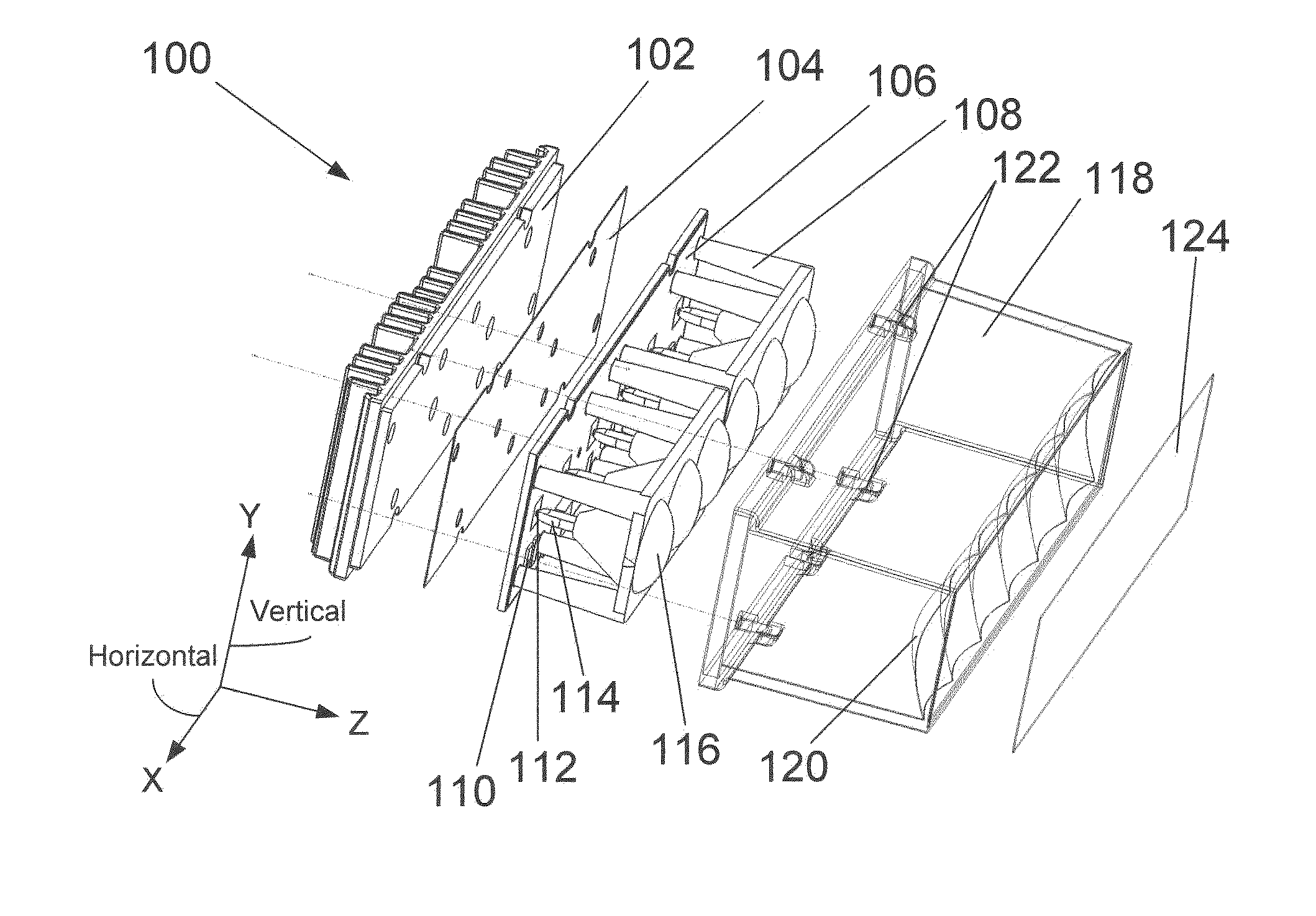
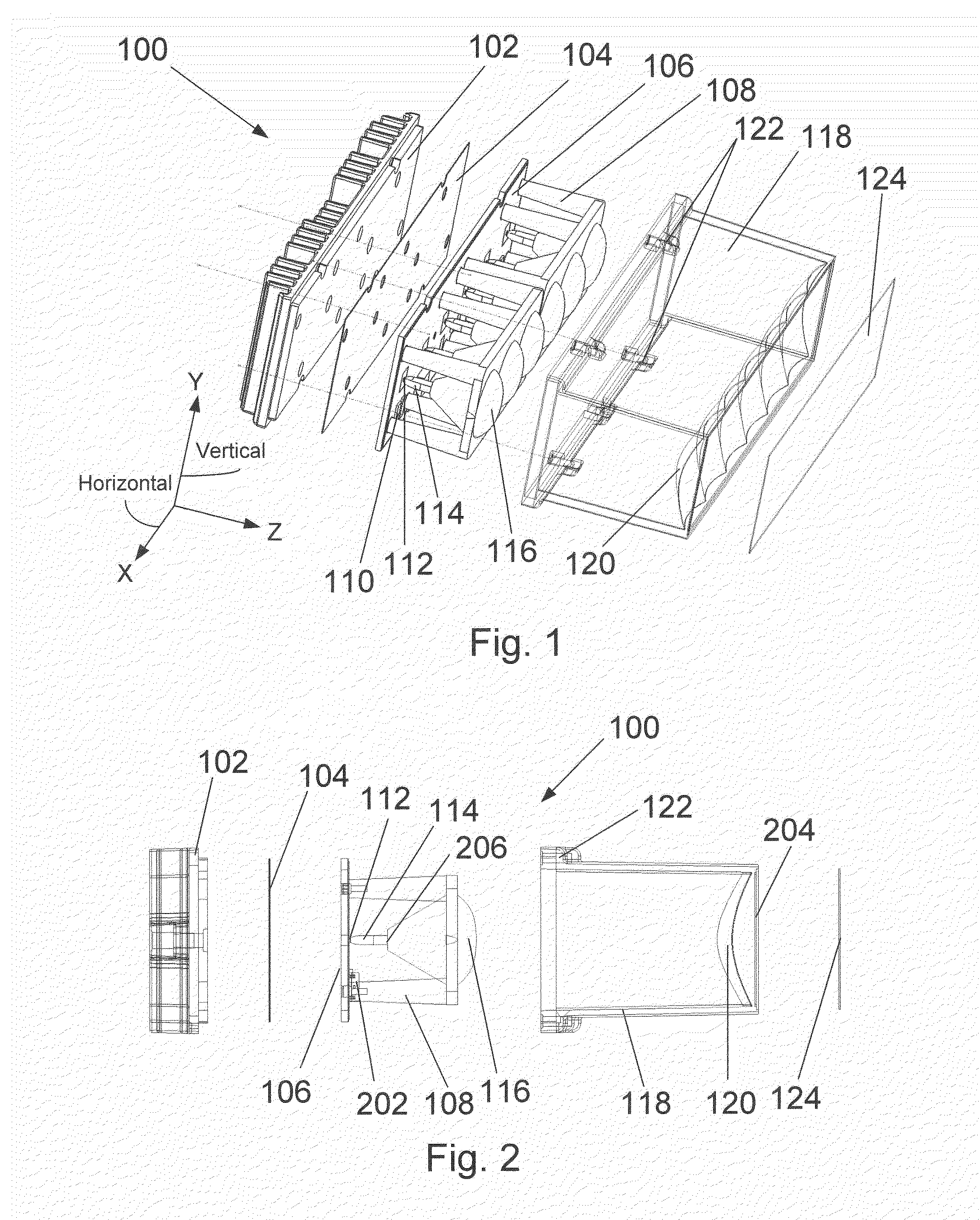
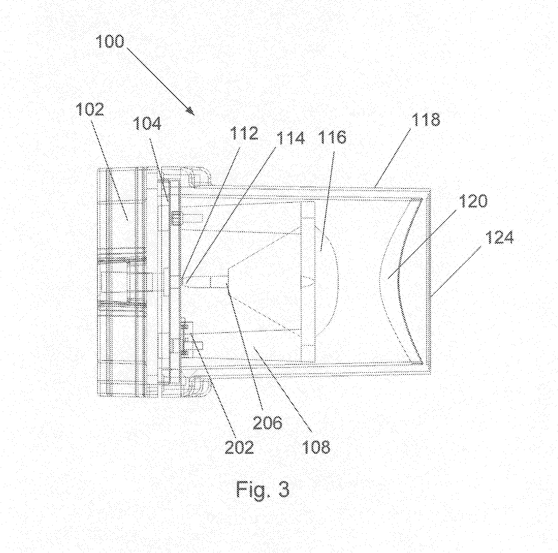
[0047]FIGS. 1, 2 and 3 show, respectively, an exploded isometric view of a preferred embodiment of the LED module designated generally at 100, an exploded view of LED module 100 in the Y-Z plane, and a collapsed side view of LED module 100 in the Y-Z plane. The LED module 100 comprises a “Chip-on-Board” (COB) metal core substrate printed circuit board (PCB) 106 with six (6) individual LED die 112 shown optically coupled to an associated individual non-imaging collecting optic section 114, one each for each LED die 112. Each non-imaging collecting optic section 114 has an input aperture on the order of the size of a square LED die 112, 1.1 mm, for example. The non-imaging collection optic section 114 is described in detail below.

[0048]The light that exi...


PUM


Abstract

LED “Chip-on-Board” (COB) metal core printed circuit board (PCB) technology operates in conjunction with high efficiency compact imaging and non-imaging optics to provide a compact emergency light offering high performance luminance levels (higher brightness) and enhanced life, at low cost. Thermal impedance between the LED junction and the heat sink is significantly reduced for COB technology by placing the LED die directly on a high thermal conductivity material substrate thereby increasing temperature dependant life and thermally dependant output power. Additionally, there is no encapsulant or domed optic over the LED thus making it possible to get a much more compact and efficient substantially Etendue preserving collection optic directly over the die.

Description

FIELD OF THE INVENTION[0001]This invention, in general, relates to emergency lighting apparatus and, more particularly, to the use of light emitting diodes (LEDs) in high luminance emergency lighting systems.BACKGROUND OF THE INVENTION[0002]High brightness light emitting diode (LED) light sources are in high demand for challenging applications including emergency lighting. Prior art in the emergency lighting field typically utilize either tungsten or tungsten halogen lamps with colored filters or, more recently, systems incorporating pre-packaged high brightness LEDs. Emergency lights are used on vehicles such as police, fire, ambulance, tow trucks, construction vehicles, plows, as well as on vehicles in the aviation and marine fields.[0003]Generally, emergency lighting is relatively narrow in spectral width, with the most widely used colors including blue, green, amber, and red. In some cases there is a demand for white light as well. Filtered halogen or tungsten halogen lamps by t...

Claims


Application Information

Patent Timeline
Patent Type & Authority Patents(United States)
IPC IPC(8): F21S4/00F21K99/00F21V5/00F21V21/00F21Y101/02
CPCF21V5/008B60Q1/2611F21K9/00F21S48/328F21V13/04F21V13/12F21V29/004F21V29/2206F21V29/24F21Y2101/02F21Y2103/003G02B19/0028G02B19/0066F21V7/005F21V7/06F21V13/14F21V29/74F21V29/763F21V29/85F21Y2103/10F21Y2115/10
Inventor BRUKILACCHIO, THOMAS, JOHN
Owner INNOVATIONS & OPTICS
Learn More