Controlling printed ink line widths using fluoropolymer templates

a template and printed ink technology, applied in the field of integrated circuit (ic) fabrication, can solve the problems of difficult reduce so as to increase the conductivity of printed metal lines, increase the line width, and add significant thickness to printed conductive lines

Inactive Publication Date: 2014-07-01
SHARP KK
View PDF6 Cites 3 Cited by
  • Summary
  • Abstract
  • Description
  • Claims
  • Application Information

AI Technical Summary

Benefits of technology

[0007]Disclosed herein is a method for adding significant thickness to a printed conductive line, without an increase in line width, by introducing a printed fluoropolymer bank structure. The printed line conductance is increased as a result of increasing the printed metal line thickness. Printed metal line thickness is increased without an increase in the printed metal line width by using a fluoropolymer bank structure that when fully processed is capable of limiting the lateral spread of the conductive metal precursor ink and enabling the use of larger volumes of this metal ink.
[0009]In one aspect, the method prints a plurality of primary ink layers, each primary ink layer having an ink width less than the template width. Advantageously, each overlying primary ink layer can be printed prior to solvents in each underlying primary ink layer evaporating. Printing the plurality of primary ink layers causes an increase in the vertical average height of the combined layer ink line following the printing of each successive primary ink layer. Further, the printing of each successive primary ink layer includes increases the average height without increasing the ink width.

Problems solved by technology

This inferior conductivity is detrimental to circuit design.
The conductivity limitations of these materials can be traced to density limitations due to voids and film porosity, as well as grain size and interface effects.
However, substrate and high temperature incompatibility of other thin film layers typically constrain the annealing time / temperature conditions that are suitable.
For these reasons, increasing the conductivity of printed metal lines is challenging.
An increase of the width of a conductive line is not typically preferred because that line will consume more substrate area and result in fewer circuits that can be physically placed on a given substrate.
However, with solution process, and printed conductive lines in particular, this is not easily achieved.

Method used


Image

  • Controlling printed ink line widths using fluoropolymer templates
  • Controlling printed ink line widths using fluoropolymer templates
  • Controlling printed ink line widths using fluoropolymer templates

Examples


Embodiment Construction

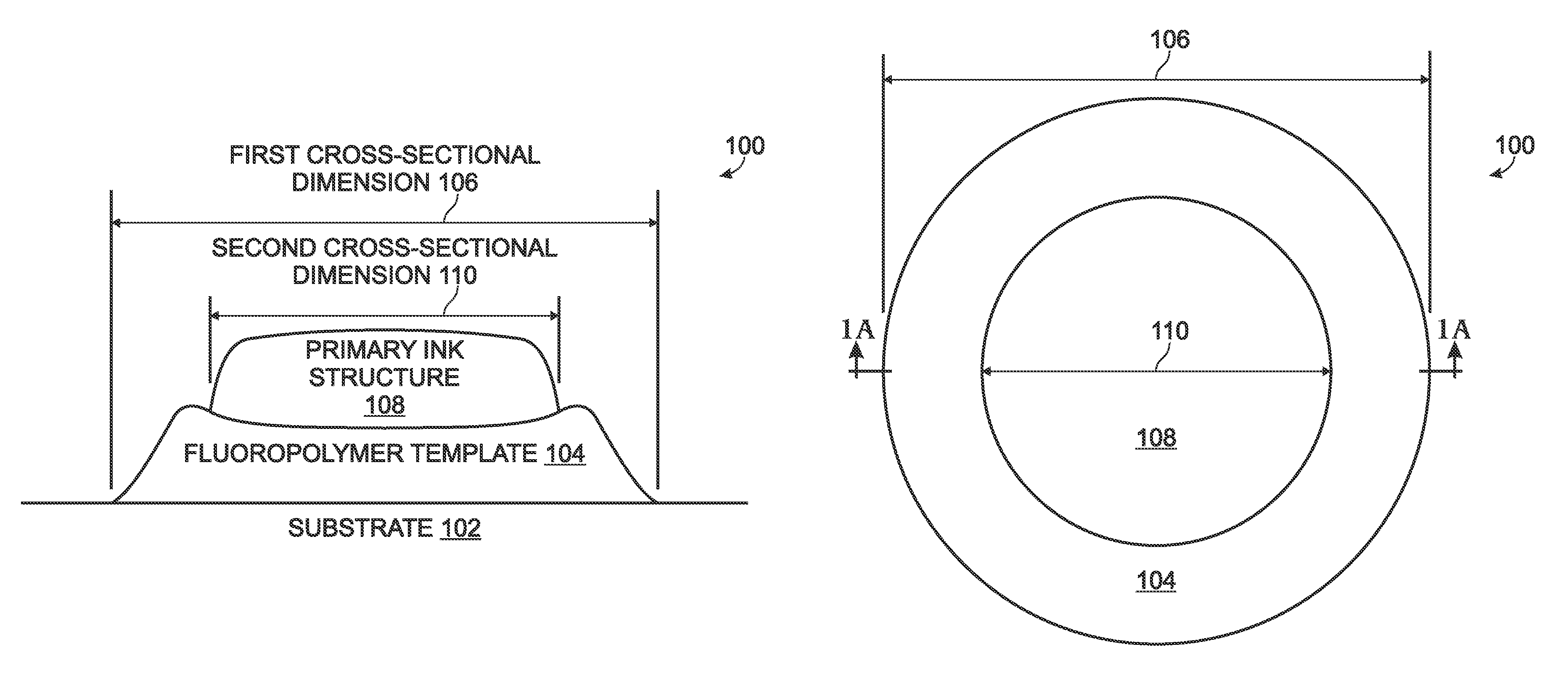
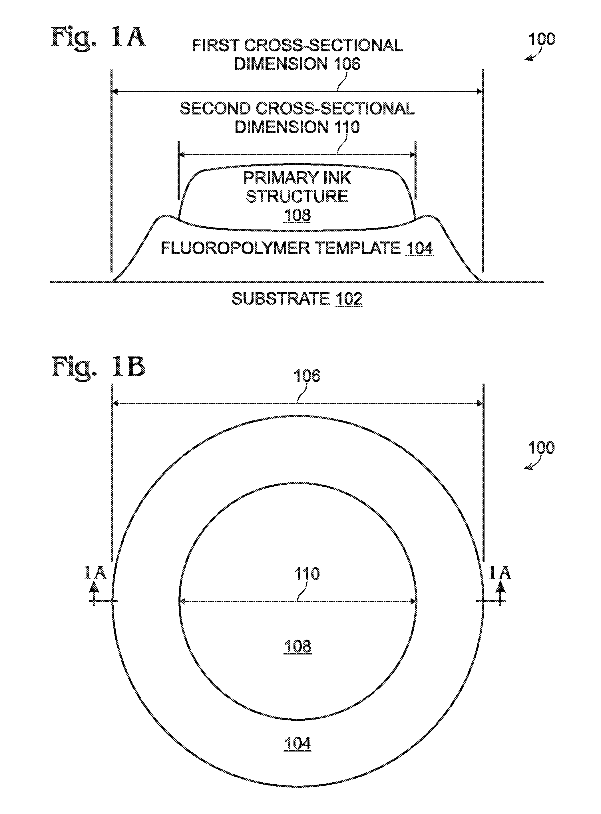
[0022]FIGS. 1A and 1B are, respectively, partial cross-sectional and plan views of a printed ink structure with a controlled horizontal cross-sectional area. The printed ink structure 100 comprises a substrate 102 and a fluoropolymer template 104 overlying the substrate 102. The fluoropolymer template 104 has a horizontal first cross-sectional dimension 106. A primary ink structure 108 overlies the fluoropolymer template and has a horizontal second cross-sectional dimension 110 less than the first cross-sectional dimension 106. In some aspects as shown, the fluoropolymer template 104 has a coffee stain pattern in the first cross-sectional dimension 106. As used herein, a coffee stain pattern is understood to a film of material with a greater thickness of material around the edge of the pattern than in the center. In other words, a coffee stain pattern resembles a pattern of spilled coffee underlying a coffee cup, after the coffee has dried. However, it should be understood that the ...


PUM

PropertyMeasurementUnit
widthaaaaaaaaaa
water contact angleaaaaaaaaaa
heightaaaaaaaaaa

Abstract

A method is provided for controlling printed ink horizontal cross-sectional areas using fluoropolymer templates. The method initially forms a fluoropolymer template overlying a substrate. The fluoropolymer template has a horizontal first cross-sectional dimension. Then, a primary ink is printed overlying the fluoropolymer template having a horizontal second cross-sectional dimension less than the first cross-sectional dimension. In the case of a fluoropolymer line having a template length greater than a template width, where the template width is the first cross-sectional dimension, printing the primary ink entails printing a primary ink line having an ink length greater than an ink width, where the ink width is the second cross-sectional dimension. In one aspect, the method prints a plurality of primary ink layers, each primary ink layer having an ink width less than the template width. Each overlying primary ink layer can be printed prior to solvents in underlying primary ink layers evaporating.

Description

BACKGROUND OF THE INVENTION[0001]1. Field of the Invention[0002]This invention generally relates to integrated circuit (IC) fabrication and, more particularly, to a method for controlling printed ink line widths using fluoropolymer templates.[0003]2. Description of the Related Art[0004]Printed electronics fabrication relies on the application of metal precursor ink formulations to produce conductive circuit elements. These metal precursor inks are applied to a substrate by inkjet printing for example, and further processing steps are required to render the printed pattern conductive. Printed metal inks, however, produce conductive lines that have conductivities that are typically on the order of 10× less conductive than bulk metals or vacuum processed thin film metal layers. This inferior conductivity is detrimental to circuit design. The conductivity limitations of these materials can be traced to density limitations due to voids and film porosity, as well as grain size and interfa...

Claims


Application Information

Patent Timeline
Patent Type & Authority Patents(United States)
IPC IPC(8): B05D5/00
CPCH05K3/125H01L51/0022H05K2203/1476H05K2201/015B41N1/00H05K2203/1173H01L51/0005H05K3/1208H10K71/135H10K71/611
Inventor ULMER, KURTPUNTAMBEKAR, KANANSTECKER, LISA H.
Owner SHARP KK
Why Eureka
Try Eureka