
Semiconductor oxide ink composition for inkjet printing, method of manufacturing the same, and method of manufacturing photoelectric conversion element using the same

a technology of inkjet printing and semiconductors, applied in the direction of electrolytic capacitors, conductors, liquid/solution decomposition chemical coatings, etc., can solve the problems of loss of original intended attractiveness of openness, increased production cost, and complex manufacturing process, so as to reduce manufacturing processes and costs

Active Publication Date: 2014-07-08
HYUNDAI MOTOR CO LTD
View PDF15 Cites 9 Cited by
  • Summary
  • Abstract
  • Description
  • Claims
  • Application Information

AI Technical Summary

Benefits of technology

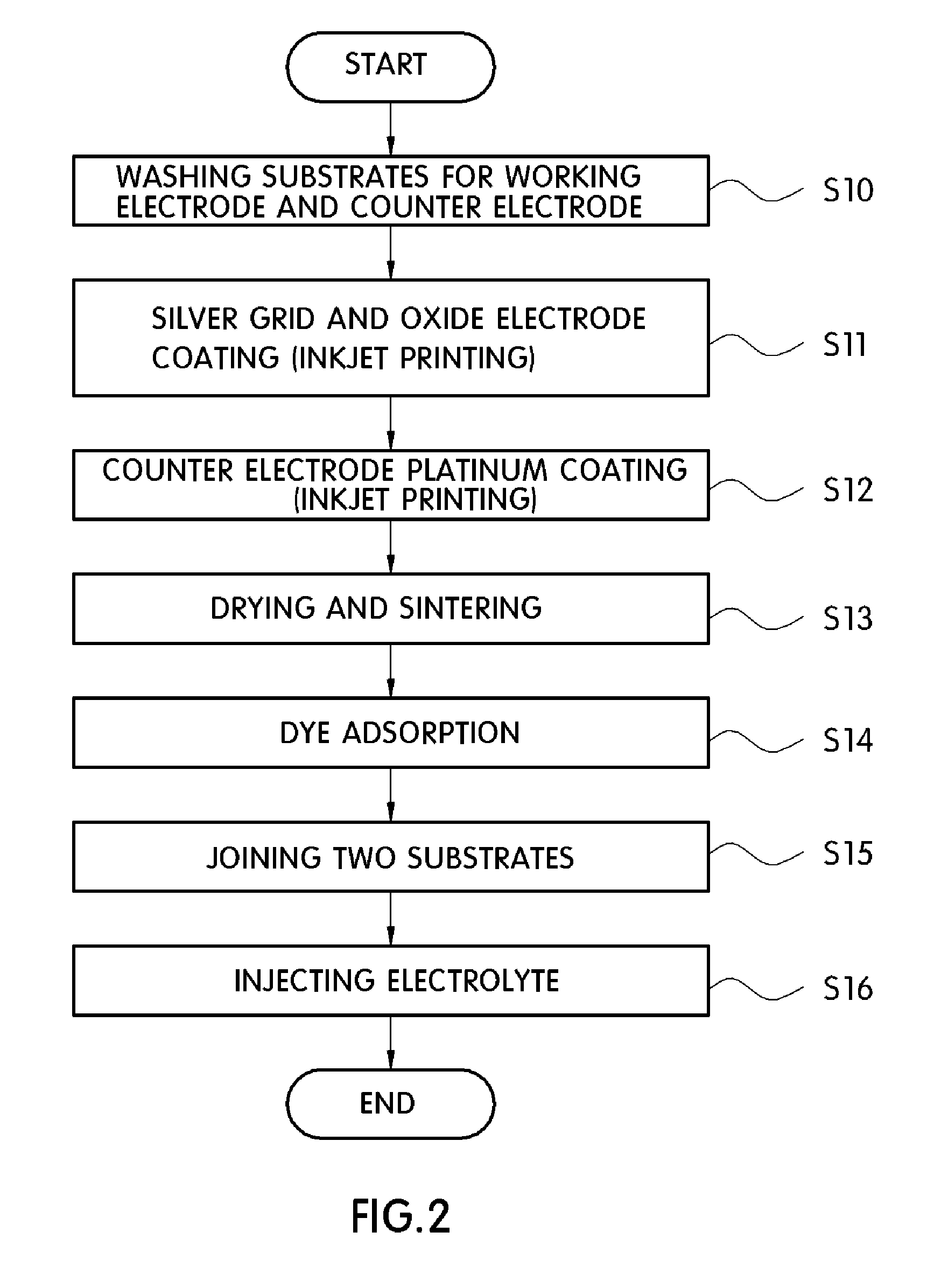
This patent describes a method for making a semiconductor oxide layer for a photoelectric conversion element using inkjet printing. This method is cost-effective and waste-reducing compared to conventional methods. The inkjet printing method can also improve the dispersability and adhesion of the semiconductor oxide layer with a substrate. This makes it easier to create photoelectric conversion elements with good performance. The patent also includes a list of suitable agents that can be added to the composition to enhance dispersability and adhesion. Overall, this patent presents a solution for manufacturing photoelectric conversion elements with efficiency and precision.

Problems solved by technology

However, this type of sunroof is opaque and, thus, loses its originally intended attractiveness of openness.
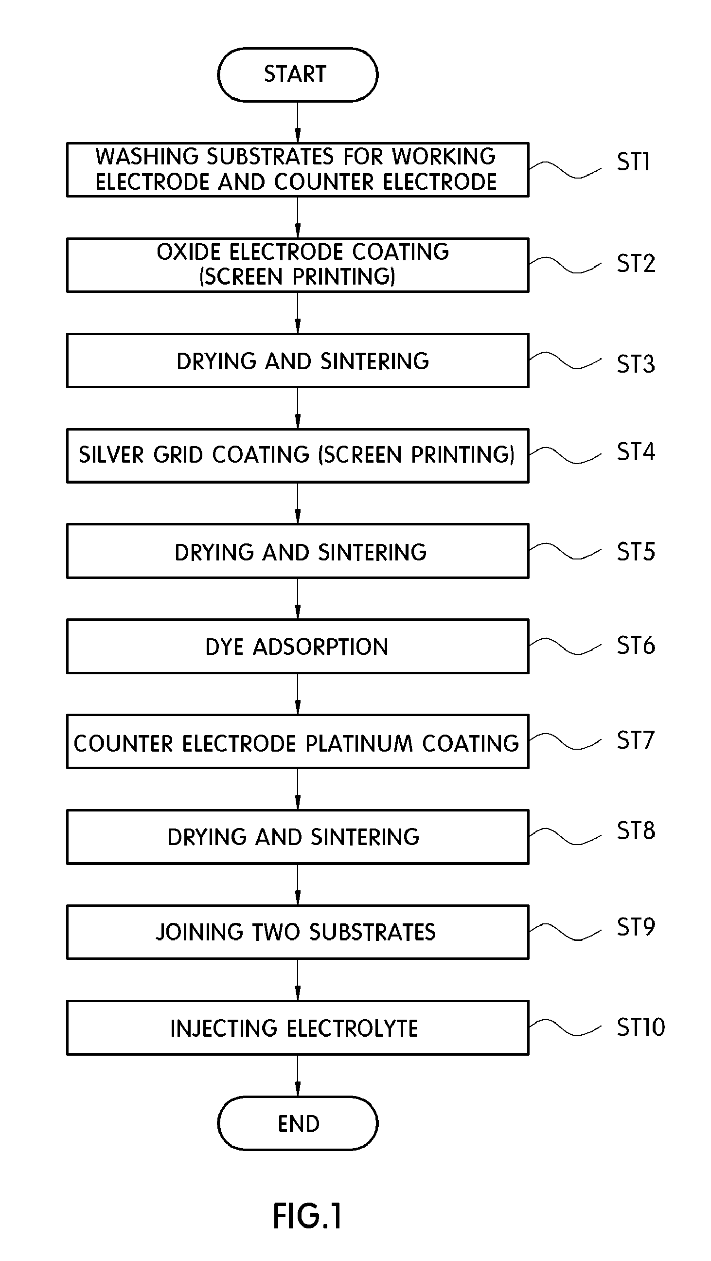
As a result, the manufacturing process becomes more complex and the production cost increases.
Moreover, if the dye-sensitized solar cell is manufactured using a curved substrate in the screen printing method, it may lead to a difference in thickness of the coating layer along the substrate surface, such as between the central portion and both ends of the substrate.
Further, if the coating process is performed at an increased squeegee pressure in an attempt to prevent such a thickness difference, the mesh may become damaged when fixed under a constant tension.
Accordingly, it is difficult to apply the screen printing method to a curved substrate.
However, the inkjet printing method may not be employed for a process of forming a layer with thickness 1 μm or larger, such as a semiconductor oxide layer used for a dye-sensitized solar cell.
Further, there is no common process to manufacture a dye-sensitized solar cell using the inkjet printing method.

Method used


Image

  • Semiconductor oxide ink composition for inkjet printing, method of manufacturing the same, and method of manufacturing photoelectric conversion element using the same
  • Semiconductor oxide ink composition for inkjet printing, method of manufacturing the same, and method of manufacturing photoelectric conversion element using the same
  • Semiconductor oxide ink composition for inkjet printing, method of manufacturing the same, and method of manufacturing photoelectric conversion element using the same

Examples


example 1

[0110]Titanium isopropoxide, water, ethanol, and nitric acid were mixed at a mole ratio of 1:1.5:20:0.08, stirred for 4 hrs, and then dried in a vacuum oven at 60° C. for 12 hrs to thereby remove the solvent.

[0111]The resultant material was washed several times by water and ethanol using a filter until pH became neutral, and then dried again in the vacuum oven at 60° C. for 24 hrs.

[0112]The TiO2 nano-particles thus acquired were added to ethanol in an amount of 10 wt %, and then a dispersing agent was further added, such as DisperBYK-180, in an amount of 2 wt % with respect to the weight of the TiO2 nano-particles, followed by circulation and dispersion by a wet-type bead mill for 1 hr.

[0113]Next, 1 wt % methyl cellulose solution (using a solvent obtained by mixing water and ethanol at a weight ratio of 5:5) was added by 5 wt % relative to the weight of the TiO2, and then dispersed for 20 min using a horn-type ultrasonic homogenizer, followed by being subjected to a 3-roll mill to a...

example 2

[0116]Titanium isopropoxide, water, ethanol, and nitric acid were mixed at a mole ratio of 1:1.5:30:0.05 and stirred for 6 hrs, and then dried in a vacuum oven at 60° C. for 12 hrs to thereby remove the solvent.

[0117]The subsequent processes were identical to those of Example 1 except that ethyl cellulose was used as the binder instead of methyl cellulose.

[0118]The thus formed TiO2 ink composition was used to form a TiO2 layer on a curved conductive layer. The resultant TiO2 layer had a thickness of 7 μm.

[0119]A transflective dye-sensitized solar cell module with a size of 100 mm×100 mm was also manufactured using the TiO2 ink composition. The resultant photoelectric conversion efficiency was 4.5%.

example 3

[0120]A semiconductor oxide sol using the same mole ratio as that in Example 2 was created, and then ethanol was removed using an evaporator.

[0121]100 g of the thus formed semiconductor oxide sol was added to a 200 g mixed solvent (a mixture of water and ethanol at a mole ratio of 3:7), followed by addition of 3 g DisperBYK-2001. The thus formed mixture was then circulated and dispersed by a wet-type bead mill for 1 hr.

[0122]Thereafter, the solvent was removed by the evaporator and 200 g of 2-methoxyethanol was added to the resultant TiO2 sol.

[0123]Subsequently, the resultant material was dispersed by a horn-type ultrasonic homogenizer for 20 min, and then added to 10 g polypropylene glycol acrylate, followed by being subjected to a 3-roll mill to adjust the viscosity to 12 cps.

[0124]The thus formed TiO2 ink composition was used to form a TiO2 layer on a curved conductive layer. The resultant TiO2 layer had a thickness of 7 μm, and the photoelectric conversion efficiency of the dye-...


PUM

PropertyMeasurementUnit
surface tensionaaaaaaaaaa
secondary particle sizeaaaaaaaaaa
thicknessaaaaaaaaaa

Abstract

A semiconductor oxide ink composition, a method of manufacturing the composition, and a method of manufacturing a photoelectric conversion element are provided. The semiconductor oxide ink composition for inkjet printing comprises a semiconductor oxide and a solvent, wherein the semiconductor oxide comprises 0.1 to 20 parts by weight relative to 100 parts by weight of the total composition.

Description

CROSS-REFERENCE TO RELATED APPLICATION[0001]This application claims under 35 U.S.C. §119(a) the benefit of Korean Patent Application No. 10-2010-0110063 filed Nov. 5, 2010, the entire contents of which are incorporated herein by reference.BACKGROUND[0002](a) Technical Field[0003]The present invention relates to a semiconductor oxide ink composition for inkjet printing, a method of manufacturing the same, and a method of manufacturing a photoelectric conversion element using the same. In particular, the present invention relates to a semiconductor oxide ink composition appropriate for inkjet printing which helps to effectively produce a photoelectric conversion element, such as a curved dye-sensitized solar cell, a method of manufacturing the semiconductor oxide ink composition, and a method of manufacturing a photoelectric conversion element using the semiconductor oxide ink composition.[0004](b) Background Art[0005]Recently, the growing interest in environmentally friendly energy h...

Claims


Application Information

Patent Timeline
Patent Type & Authority Patents(United States)
IPC IPC(8): B05D5/12H01B1/20B41J2/01C09D11/00C09D11/322C09D11/326C09D11/38H01L31/04H01M14/00H10K99/00
CPCH01L51/0022Y02E10/542C23C18/1216H01G9/2031C01G23/053H01L51/0086C01P2004/64C01P2002/72Y02T10/88H01L51/0005C09D11/52Y02E10/549C09D11/322B82Y30/00C23C18/125H01G9/2022H10K71/135H10K71/611H10K85/344
Inventor KIM, WON JUNGKIM, SANG HAKJANG, YONG JUNKIM, YONG GUSONG, MI YEONSONG, IN WOOLEE, KI CHUN
Owner HYUNDAI MOTOR CO LTD
Learn More